
Composite magnetic material, buried-coil magnetic element using same, and method for producing same

a technology of buried coil and magnetic element, which is applied in the direction of inductance, magnetic core inductance, transportation and packaging, etc., can solve the problems of reducing magnetic permeability, reducing magnetic permeability, and reducing magnetic permeability, so as to achieve good withstand voltage and high magnetic permeability. , the effect of high magnetic permeability

Inactive Publication Date: 2014-09-25
PANASONIC INTELLECTUAL PROPERTY MANAGEMENT CO LTD
View PDF13 Cites 23 Cited by
  • Summary
  • Abstract
  • Description
  • Claims
  • Application Information

AI Technical Summary

Benefits of technology

The present invention relates to a composite magnetic material that can be used to make a buried-coil magnetic element. By using this composite magnetic material, the magnetic element can be made smaller, have high magnetic permeability, and have improved withstand voltage. This means that the magnetic element can be used in smaller sizes without sacrificing its performance. Additionally, the use of this composite magnetic material can increase the efficiency of the circuit and decrease the loss of DC current. Overall, the invention provides a solution to create magnetic elements that are both small and highly efficient.

Problems solved by technology

Withstand voltage is a disadvantage of a conventional magnetic element.
However, this is not preferable because it results in a larger magnetic element.
However, this may decrease magnetic permeability.
However, DC current loss increases due to increased number of copper coil windings, resulting in reducing circuit efficiency.

Method used


Image

  • Composite magnetic material, buried-coil magnetic element using same, and method for producing same
  • Composite magnetic material, buried-coil magnetic element using same, and method for producing same
  • Composite magnetic material, buried-coil magnetic element using same, and method for producing same

Examples


first exemplary embodiment

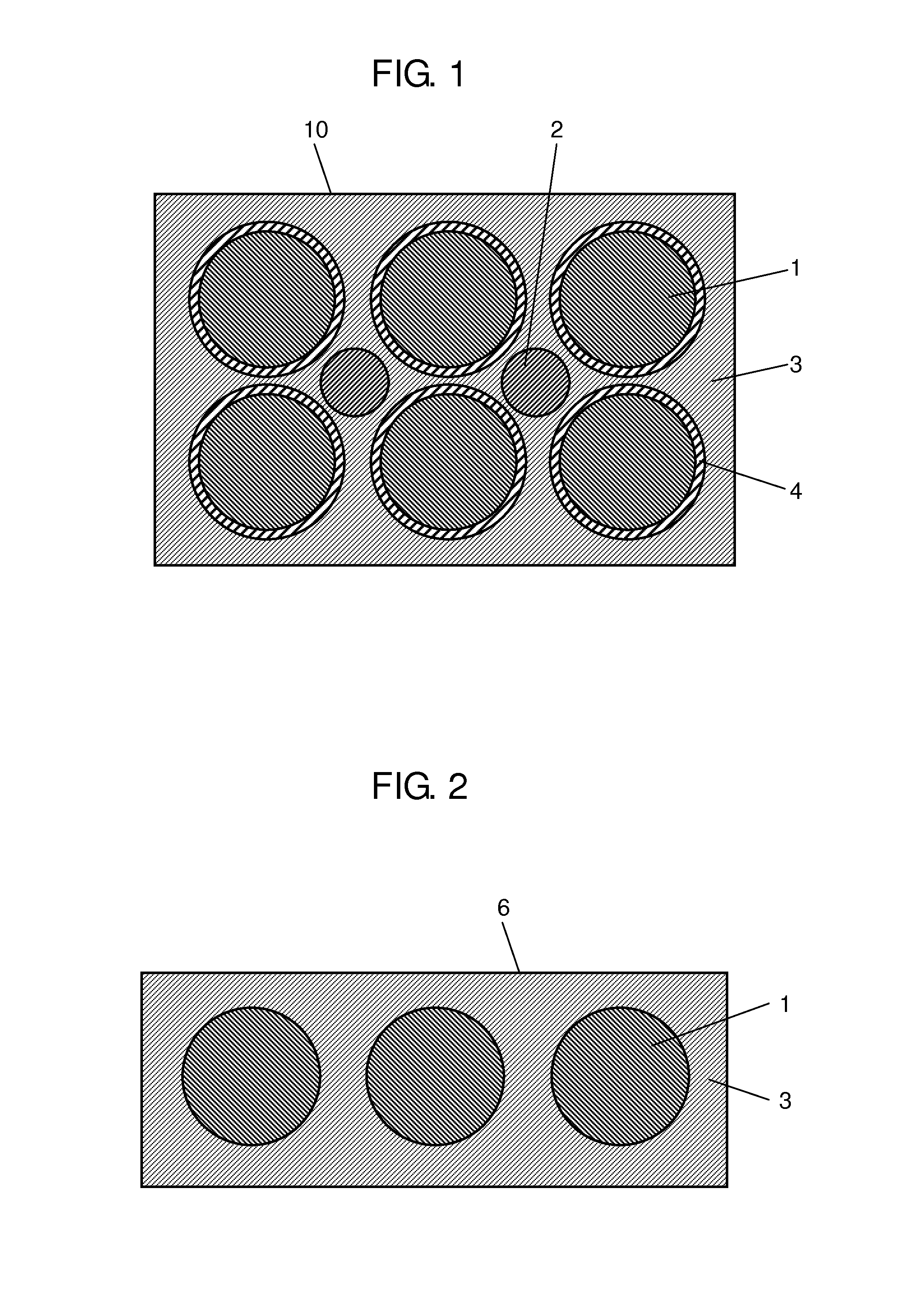
[0024]High magnetic permeability can be secured by using a composite magnetic material of two types of metal powder with different mean particle diameters. This is because second metal magnetic powder with small mean particle diameter enters a space formed between first metal magnetic powder particles with large mean particle diameter, and thus a filling rate of the metal magnetic material can be improved. As a result, high magnetic permeability can be achieved. However, since the distance between metal magnetic powder particles becomes shorter, withstand voltage of the composite magnetic material reduces. The inventor has focused on this phenomenon, and invented a composite magnetic material with high magnetic permeability and also high withstand voltage.

[0025]FIG. 1 is a schematic view of the composite magnetic material in the exemplary embodiment. As shown in FIG. 1, composite magnetic material 10 includes first metal magnetic powder 1, second metal magnetic powder 2, thermosetti...

first experiment

[0051]The composite magnetic material in the exemplary embodiment is used in the first experiment. FIG. 6 shows results of the first experiment using specimen Nos. 1 to 18 (table in FIG. 6 is hereinafter referred to as Table 1).

[0052]In the first experiment, first metal magnetic powder 1 is Fe—Si—Cr based metal magnetic powder with mean particle diameter of 10 μm, and second metal magnetic powder 2 is iron metal magnetic powder with mean particle diameter of 1 μm, 5 μm and 10 μm. A mixture is prepared by mixing 3 g of silicone resin as thermosetting resin 3 to 100 g of this iron-base metal magnetic powder. For first metal magnetic powder 1, one on which oxide film 4 is formed at ordinary temperature in the air and one on which oxide film 4 is intentionally formed at high temperature in the air are used. Vickers hardness of first metal magnetic powder 1 is 300 Hv, and Vickers hardness of second metal magnetic powder 2 is 100 Hv in the first experiment. The mixture prepared as above i...

second experiment

[0059]The second experiment uses a composite magnetic material in the exemplary embodiment same as the first experiment. FIG. 7 shows results of the second experiment using Specimen Nos. 19 to 28 (table in FIG. 7 is hereinafter referred to as Table 2).

[0060]In the second experiment, first metal magnetic powder 1 is Fe—Si—Cr based metal magnetic powder with mean particle diameter of 5 μm, and second metal magnetic powder 2 is iron metal magnetic powder with mean particle diameter of 1 μm, 2.5 μm and 5 μm. A mixture is prepared by mixing 3 g of silicone resin as thermosetting resin 3 to 100 g of this iron-base metal magnetic powder. For first metal magnetic powder 1, one on which oxide film 4 is formed at ordinary temperature in the air and one on which oxide film 4 is intentionally formed at high temperature in the air are used. Vickers hardness of first metal magnetic powder 1 and second metal magnetic powder 2 is the same as that indicated in the results of the first experiment, re...


PUM

PropertyMeasurementUnit
Temperatureaaaaaaaaaa
Percent by massaaaaaaaaaa

Abstract

A composite magnetic material includes metal magnetic powder and thermosetting resin. The metal magnetic powder includes first metal magnetic powder and second metal magnetic powder. The first metal magnetic powder includes iron and a first element with oxygen affinity higher than that of iron. The second metal magnetic powder includes at least iron. The second metal magnetic powder also includes the first element for an amount smaller than the first element contained in the first metal magnetic powder, or not include the first element. A mean particle diameter of the first metal magnetic powder is greater than a mean particle diameter of the second metal magnetic powder. The second metal magnetic powder is 10 weight % to 30 weight % of the total amount of the metal magnetic powder. This composite magnetic material can secure high magnetic permeability and also improve withstand voltage.

Description

TECHNICAL FIELD[0001]The present invention relates to composite magnetic materials typically used for inductors, choke coils, and transformers; magnetic elements using same, and methods for producing same.BACKGROUND ART[0002]In line with the recent trend of smaller and shorter electronics, there have also been increasing demands for smaller and shorter electronic components and devices used in these electronics. On the other hand, LSIs, such as CPUs, are becoming faster and higher density integration. In some cases, several amps to several tens of amps of current are supplied to power circuits for these LSIs. Therefore, smaller magnetic elements that suppress reduction of inductance due to DC superimposition are also demanded for use in these components. Furthermore, higher working frequency also requires low loss in a high-frequency region.[0003]A powder magnetic core manufactured by compression-molding metal magnetic powder has good DC superimposition characteristics, and can thus...

Claims


Application Information

Patent Timeline
IPC IPC(8): H01F1/22H01F41/02B22F1/052B22F1/10B22F1/16
CPCC22C38/00H01F41/0246H01F1/33C22C38/02C22C38/08C22C38/18B22F1/0014B22F1/0059C22C33/0207H01F1/22H01F41/02H01F17/04H01F27/292H01F2017/048H01F1/26B22F2998/10B22F2999/00C22C19/03C22C38/34B22F1/052B22F1/16B22F1/10B22F2201/50B22F1/142B22F9/04B22F1/09B22F3/02B22F2003/248B22F1/107
Inventor KOTANI, JUNICHIMATSUTANI, NOBUYA
Owner PANASONIC INTELLECTUAL PROPERTY MANAGEMENT CO LTD
Learn More