
Dynamic balance detecting device

a detection device and dynamic balance technology, applied in the direction of measurement devices, structural/machine measurement, instruments, etc., can solve the problems of vibration when a rotor rotates, affecting the lifetime and machining accuracy of machines, and vibration of detecting devices with complex structures

Inactive Publication Date: 2014-09-25
JIZHUN PRECISION IND HUIZHOU
View PDF7 Cites 5 Cited by
  • Summary
  • Abstract
  • Description
  • Claims
  • Application Information

AI Technical Summary

Benefits of technology

The patent text discusses how rotor vibrations can impact the lifespan and performance of machines. Unstable rotor positions caused by non-uniform mass distribution or installation tolerances can be measured using dynamic balance detection devices. These devices can be used to adjust the rotor's balance by adding or reducing balancing weight blocks at appropriate positions. However, current dynamic balance detection devices have complex structures and can vibrate significantly during use, which can affect the accuracy of measurements and regulation. The technical effect of this patent is to provide a more accurate and reliable method for detecting and addressing rotor unbalances in machines.

Problems solved by technology

Rotor vibrations affect the lifetime and machining accuracy of machines.
Non-uniform distributions of mass about the spin axis, installation tolerance can cause vibrations when a rotor rotates.
However, known dynamic balance detecting devices have complex structures and vibrate significantly when in use, which affects accuracies of the measurements and regulating.

Method used


Image

  • Dynamic balance detecting device
  • Dynamic balance detecting device

Examples


Embodiment Construction

[0008]The disclosure is illustrated by way of example and not by way of limitation in the figures of the accompanying drawings in which like references indicate similar elements. It should be noted that references to “an” or “one” embodiment in this disclosure are not necessarily to the same embodiment, and such references mean “at least one.”

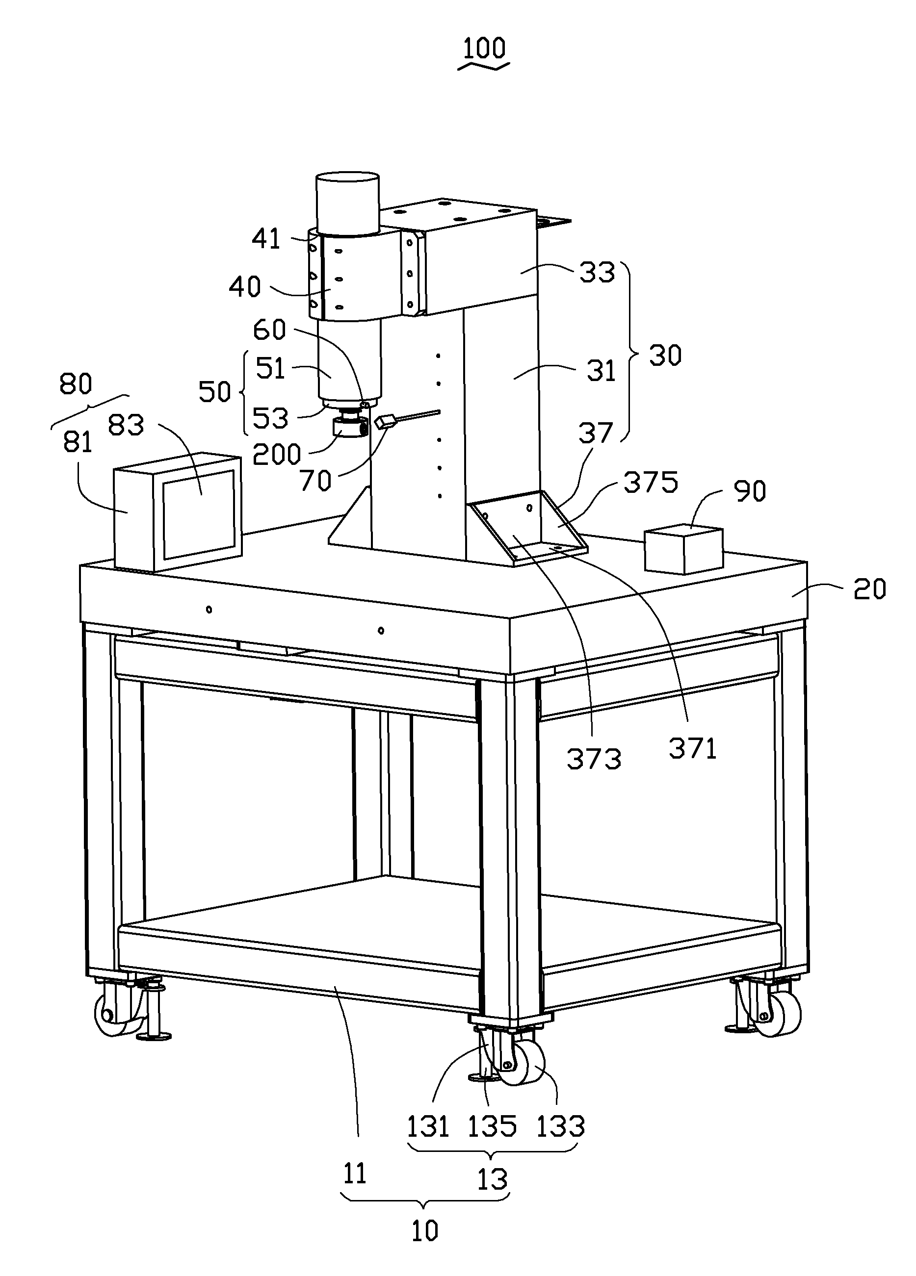
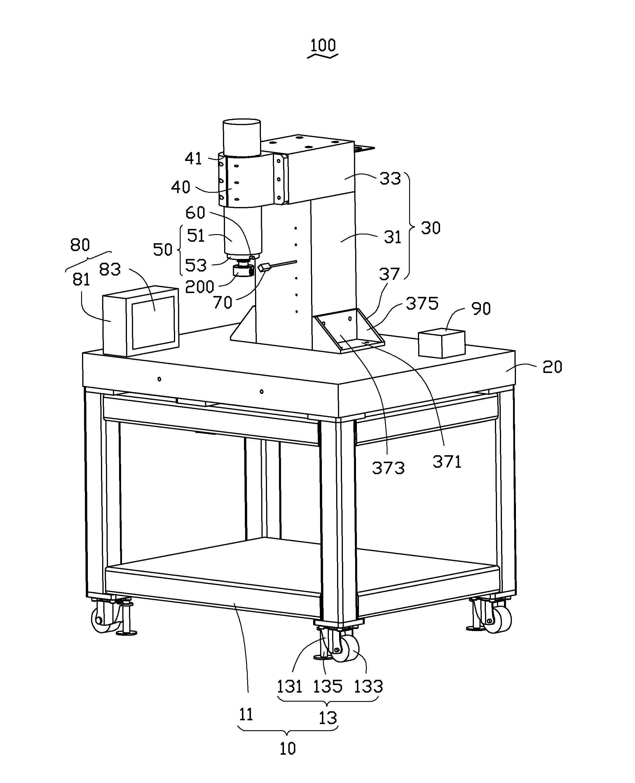
[0009]The FIGURE shows a dynamic balance detecting device 100 for detecting and regulating a dynamic balance of a rotor 200. The dynamic balance detecting device 100 includes a support frame 10, a platform 20, a pillar 30, an installation base 40, a main shaft 50, a vibration sensor 60, a rotation sensor 70, a dynamic measuring tester 80, and a controller 90. The platform 20 is supported on the support frame 10. The pillar 30 is connected substantially perpendicularly to the platform 20. The main shaft 50 is connected to the pillar 30 by the installation base 40. The rotor 200 is assembled to the main shaft 50. The main shaft 50 is capable of r...


PUM


Abstract

The dynamic balance detecting device includes a platform, a pillar, a main shaft, a vibration sensor, a rotation sensor, a dynamic measuring tester, and a controller. The pillar is connected to the platform. The main shaft is positioned on the pillar for driving a rotor. The vibration sensor is positioned adjacent to the main shaft for detecting vibration amount of the main shaft. The rotation sensor is positioned adjacent to the main shaft and spaced from the vibration sensor for detecting a rotation of the main shaft. The dynamic measuring tester is positioned on the platform for receiving vibration data obtained by the vibration sensor and rotation data obtained by the rotation sensor in real time to analyze and determine whether dynamic balance of the rotor achieving as required, and calculates a dynamic balance regulating amount for the rotor.

Description

BACKGROUND[0001]1. Technical Field[0002]The present disclosure generally relates to detecting devices, and particularly to a dynamic balance detecting device for rotors.[0003]2. Description of the Related Art[0004]Rotor vibrations affect the lifetime and machining accuracy of machines. Non-uniform distributions of mass about the spin axis, installation tolerance can cause vibrations when a rotor rotates. An unbalanced position and amount of the unbalance of the rotor can be measured by dynamic balance detecting devices. The unbalance of the rotor is lowered by adding or reducing balancing weight block at appropriate positions. However, known dynamic balance detecting devices have complex structures and vibrate significantly when in use, which affects accuracies of the measurements and regulating.[0005]Therefore, there is room for improvement within the art.BRIEF DESCRIPTION OF THE DRAWING[0006]The components in the drawings are not necessarily drawn to scale, the emphasis instead be...

Claims


Application Information

Patent Timeline
Patent Type & Authority Applications(United States)
IPC IPC(8): G01M1/16
CPCG01M1/16G01M1/22
Inventor LIU, GANGDING, JI-DONGZHANG, JUNWANG, XIAO-DONGZHANG, GUO-XUANPENG, XUE-FEIHE, ZHONG-HUA
Owner JIZHUN PRECISION IND HUIZHOU
Learn More