
Integrated catheter and powered injector system for use in performing radial angiography

a radial angiography and powered injection technology, which is applied in the field of coronary angiography, can solve the problems of difficult access to the radial artery with a catheter, the inability to manually inject contrast media into such a tiny diameter and at a controlled (or steady) rate and pressure, and the inability to use the contrast media manually, etc., to achieve the effect of eliminating cords, reducing the number of connections, and convenient us

Inactive Publication Date: 2014-09-18
SYNTHEON
View PDF6 Cites 6 Cited by
  • Summary
  • Abstract
  • Description
  • Claims
  • Application Information

AI Technical Summary

Benefits of technology

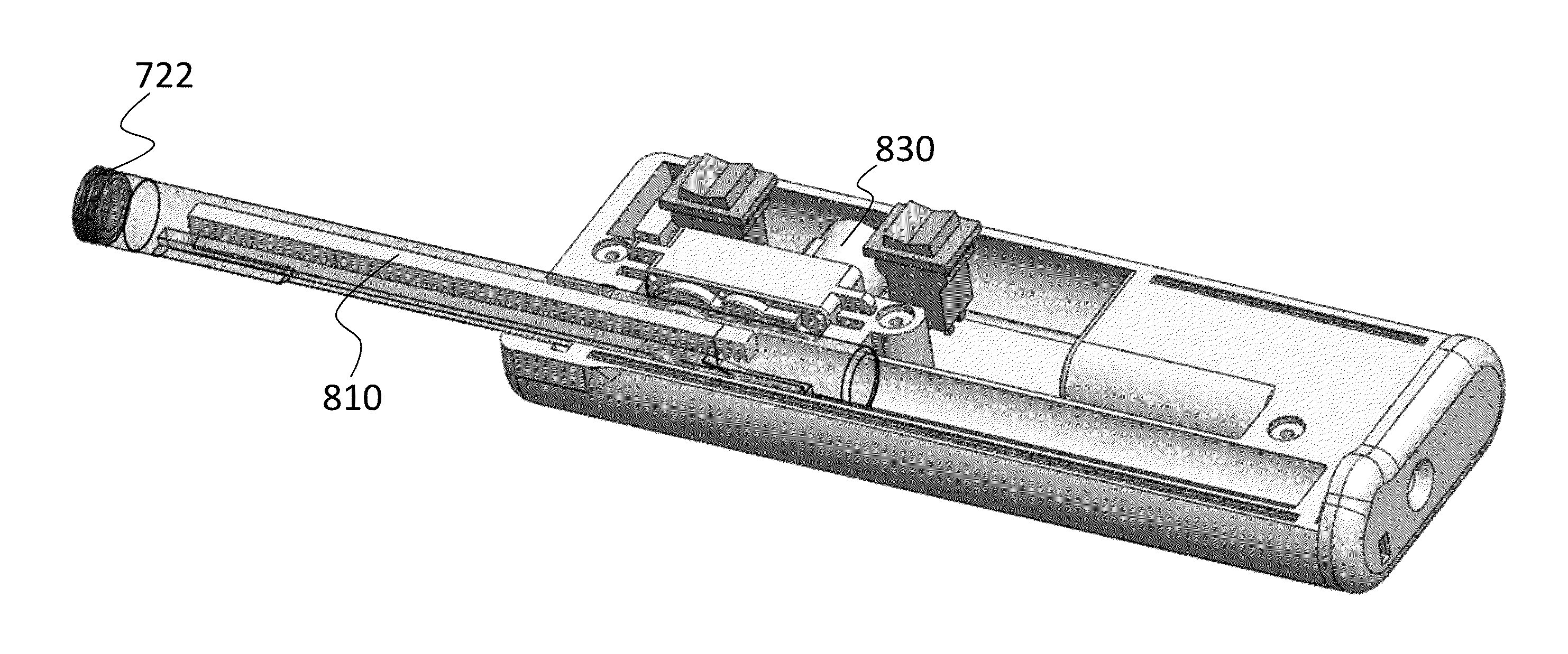
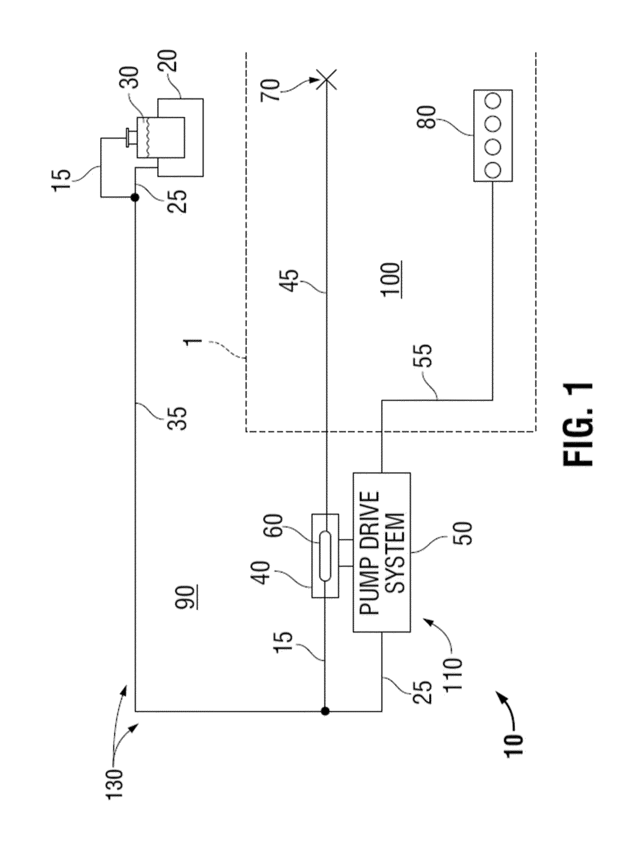
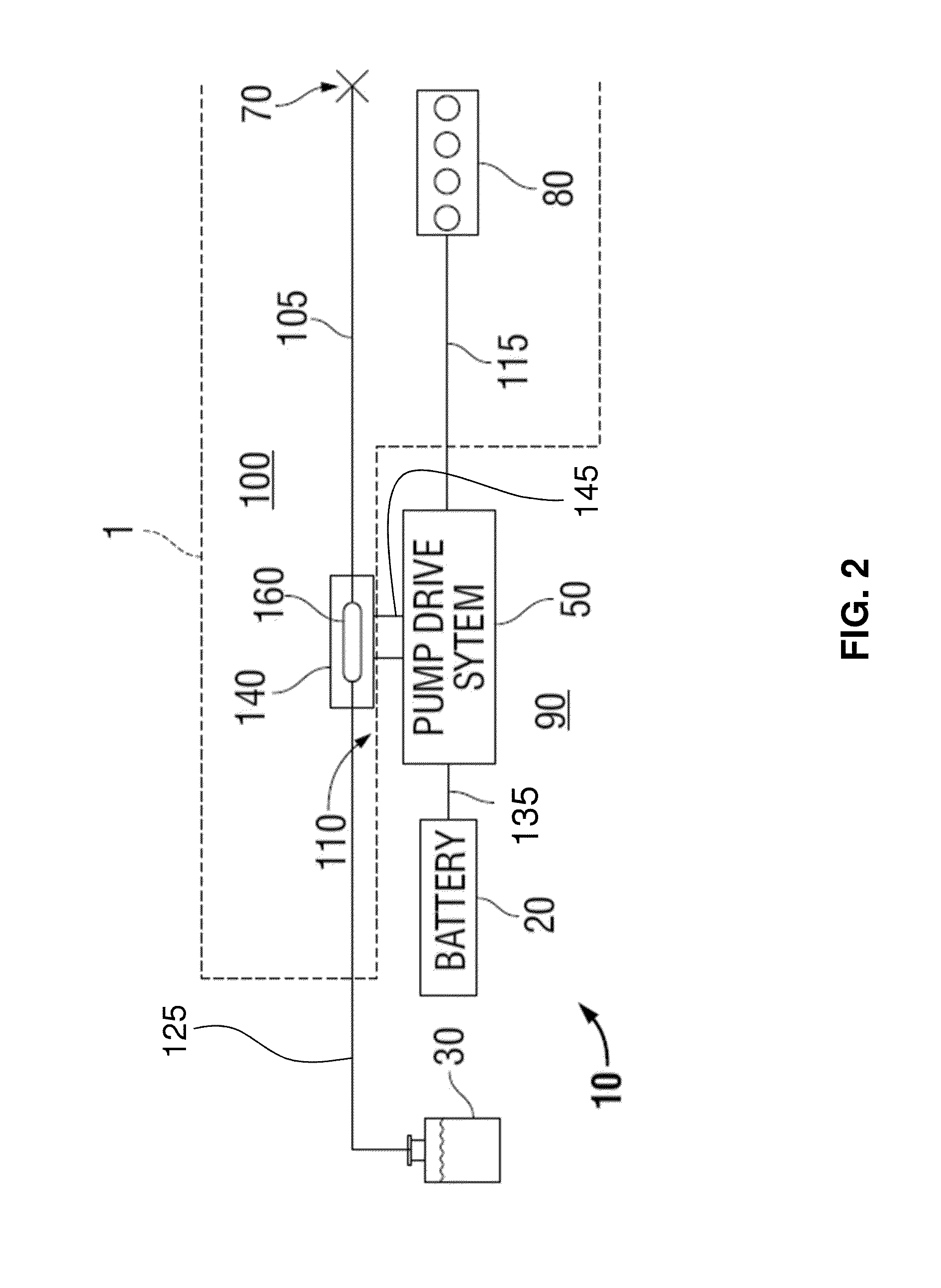
The present invention is a new and improved injection system that is easier to use and more compact. It is designed to be operated directly by a physician and is an all-in-one system, meaning it requires fewer connections between its components and eliminates cords and traditional powered injector equipment. This simplifies the system and makes it more efficient.

Problems solved by technology

Still, there are several disadvantages associated with radial angiography, as well.
Accordingly, it is difficult to access the radial artery with a catheter and to inject the contrast media at a pressure and flow rate that approximates or falls within the pressure tolerances of the radial artery.
Entry into the radial artery is even more difficult for women as the radial artery is even smaller, generally speaking, in women than in men.
Yet, by using the appropriate catheter, it then becomes impossible to manually inject the contrast media into such a tiny diameter and at a controlled (or steady) rate and pressure.
If a catheter having too large of a diameter is used or, if the contrast media is injected into smaller catheter at a rate or pressure that is too high, a number of complications can occur.
Examples of the more dangerous complications include extensive hemorrhaging, damage or paralysis of the nerves surrounding the artery, and the formation of a blood clot (thrombus) in the artery.
With the introduction of a powered injector device, there is an added operational complexity and expense because an entire system must be put into place in order to incorporate the powered injector device.

Method used


Image

  • Integrated catheter and powered injector system for use in performing radial angiography
  • Integrated catheter and powered injector system for use in performing radial angiography
  • Integrated catheter and powered injector system for use in performing radial angiography

Examples


Embodiment Construction

[0053]As required, detailed embodiments of the present invention are disclosed herein; however, it is to be understood that the disclosed embodiments are merely exemplary of the invention, which can be embodied in various forms. Therefore, specific structural and functional details disclosed herein are not to be interpreted as limiting, but merely as a basis for any claims and as a representative basis for teaching one skilled in the art to variously employ the present invention in virtually any appropriately detailed structure. Further, the terms and phrases used herein are not intended to be limiting; but rather, to provide an understandable description of the invention. While the specification may conclude with claims defining the features of the invention that are regarded as novel, it is believed that the invention will be better understood from a consideration of the following description in conjunction with the drawing figures, in which like reference numerals are carried for...


PUM


Abstract

An integrated catheter and powered injector system includes a pump housed in a self-contained unit, a contrast media supply removably connected to the pump by a fluid supply line, an extension line removably connecting an arterial catheter to the pump, and a control device sending user control signals to the pump. The pump comprises a motorized pump drive sub-system operating the pump, and a battery electrically connected to and powering the pump drive sub-system. In response to signals received from the control device, the pump drive sub-system drives the pump to draw contrast media fluid from the supply into the pump through the fluid supply line and inject the contrast media fluid from the output of the pump through the extension line and into the arterial catheter at a controlled flow rate and / or pressure.

Description

CROSS-REFERENCE TO RELATED APPLICATIONS[0001]This application claims priority to U.S. Provisional Application Ser. No. 61 / 787,044, filed on Mar. 15, 2013, and 61 / 824,362, filed on May 16, 2013, the entire disclosures of which are hereby incorporated herein by reference in their entirety.STATEMENT REGARDING FEDERALLY SPONSORED RESEARCH OR DEVELOPMENT[0002]Not ApplicableFIELD OF THE INVENTION[0003]The present invention lies in the field of coronary angiography. In particular, the present invention provides an integrated “one-stop” catheter and powered injector system that is comprised of substantially all of the necessary devices and sub-systems (e.g., a set of catheters of various sizes and geometric configurations and their associated introducer sheaths, a set of angiographic syringes of different designs and sizes, and a battery-powered injector device) needed to perform a coronary angiography procedure through the radial artery of a patient.BACKGROUND OF THE INVENTION[0004]Million...

Claims


Application Information

Patent Timeline
IPC IPC(8): A61M5/00A61M5/145
CPCA61M5/007A61M5/14546A61M2205/8206A61M2202/0007A61M2005/14506A61M5/14216A61M5/14232A61M5/14244
Inventor SMITH, KEVIN W.BALES, JR., THOMAS O.KLINE, KOREYPALMER, MATTHEW A.MCBRAYER, SEANDEVILLE, DEREK DEEPETERSEN, ERIC
Owner SYNTHEON
Learn More