
Charging member, process cartridge, and electrophotographic image forming apparatus

Active Publication Date: 2014-09-18
CANON KK
View PDF3 Cites 7 Cited by
  • Summary
  • Abstract
  • Description
  • Claims
  • Application Information

AI Technical Summary

Benefits of technology

The present invention aims to provide a charging member that has stable electric resistance over a long period of use, which prevents image defects caused by changes in electric resistance. Additionally, the invention also provides a process cartridge and electrophotographic apparatus that can consistently produce high-quality electrophotographic images.

Problems solved by technology

H03-9380 still caused charging defects due to changes in electric resistance over time in some cases.
H03-9380 has reduced antioxidizing ability of the hindered phenol compound due to generation of NOx during charging, resulting in changes in electric resistance over time.
Consequently the charging evenness is impaired.

Method used


Image

  • Charging member, process cartridge, and electrophotographic image forming apparatus
  • Charging member, process cartridge, and electrophotographic image forming apparatus
  • Charging member, process cartridge, and electrophotographic image forming apparatus

Examples


example 1

Manufacturing of Elastic Roller

[0108]An elastic roller having an elastic layer on an electroconductive support was manufactured as follows.

[0109]To a stainless steel rod having a diameter of 6 mm and a length of 252.5 mm was coated with a thermosetting adhesive (trade name: METALOC U-20, made by Toyokagaku Kenkyusho Co., Ltd.), which was then dried for use as the electroconductive support.

[0110]In manufacturing a raw material rubber composition for the rubber elastic layer, the materials shown in the following Table 4 were kneaded for 15 minutes with a closed type mixer having a capacity of 6 litters, adjusted at 50° C. In Table 4, EO represents ethylene oxide, EP represents epichlorohydrin, and AGE represents allyl glycidyl ether.

TABLE 4Parts byMaterialmassEpichlorohydrin rubber100.0(EO-EP-AGE ternary compound, EO / EP / AGE = 73 mol % / 23 mol % / 4 mol %)Calcium carbonate60.0Aliphatic polyester based plasticizer10.0(trade name: POLYCIZER P-202,made by DIC Corporation)Zinc stearate1.02-Me...

examples 2 to 5

Manufacturing of Charging Rollers (2) to (5)

[0123]Except that the amount of epigallocatechin gallate added for use in manufacturing the surface layer coating material (1) was changed as described in Table 8, charging rollers (2) to (5) were obtained by the same method as in Example 1.

example 6

Manufacturing of Charging Roller (6)

[0124]Except that the surface layer coating material (1) was changed to the following surface layer coating material (2), a charging roller (6) was obtained by the same method as in Example 1.

[0125]

[0126]A surface layer coating material including a nylon resin as binder resin was prepared as follows.

[0127]Firstly, 200 g of the mixed solution including the materials described in the following Table 7 and 200 g of glass beads as a dispersion medium having a central particle diameter of 0.6 mm to 0.85 mm (glass beads remained on a mesh having an aperture of 0.65 mm after screening with a mesh having an aperture of 0.85 mm and further screening with a mesh having an aperture of 0.65 mm) were placed in a glass bottle having a capacity of 450 mL, and dispersed for 24 hours with a paint shaker, so that a dispersion liquid was obtained.

TABLE 7Parts byMaterialmassN-methoxy methylated nylon100Carbon black (trade name: “#52”, made45by Mitsubishi Chemical Cor...


PUM

PropertyMeasurementUnit
Photosensitivityaaaaaaaaaa

Abstract

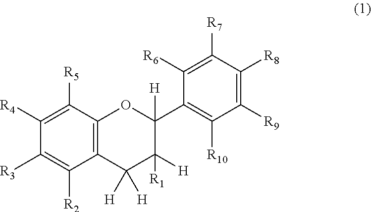
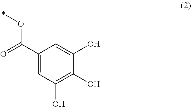
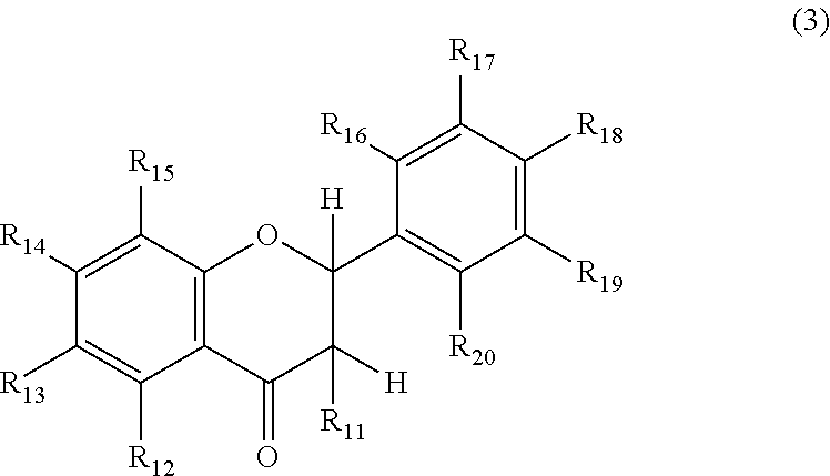
A charging member is provided, suppressing the occurrence of streak-like images resulting from resistance increase caused by degradation of the charging member due to electric conduction for a long period. A process cartridge and an electrophotographic apparatus are also provided, suppressing the occurrence of streak-like images and stably forming a high-quality electrophotographic image.The charging member comprises an electroconductive support and an electroconductive surface layer, the surface layer comprising at least one of the compounds respectively represented by formula (1), formula (3), and formula (4) defined in the specification, a binder resin, and a conducting agent. The process cartridge and the electrophotographic apparatus use the charging member.

Description

CROSS-REFERENCE TO RELATED APPLICATIONS[0001]This application is a continuation of International Application No. PCT / JP2013 / 007552, filed Dec. 24, 2013, which claims the benefit of Japanese Patent Application No. 2012-285242, filed Dec. 27, 2012.BACKGROUND OF THE INVENTION[0002]1. Field of the Invention[0003]The present invention relates to a charging member, a process cartridge, and an electrophotographic image forming apparatus.[0004]2. Description of the Related Art[0005]In an image forming apparatus using an electrophotographic method, a charging member allows an electrophotographic photosensitive member (hereinafter also referred to as “photosensitive member”) to be charged to a predetermined potential. The charging member usually includes an elastic body such as rubber or elastomer of which surface is provided with a surface layer of, for example, cross-linked urethane. A conducting agent is dispersed in the surface layer so as to impart conductivity.[0006]Due to electric ener...

Claims


Application Information

Patent Timeline
IPC IPC(8): B05C1/08B32B27/40G03G15/02
CPCG03G15/0208G03G15/0233Y10T428/31551
Inventor MATSUDA, HIDEKAZUMIYAGAWA, NOBORU
Owner CANON KK
Learn More