
Noise suppression system

a technology of noise suppression and cooling system, which is applied in the direction of machines/engines, liquid fuel engines, mechanical equipment, etc., can solve the problems that the fan (sometimes referred to as the “blower”) used in the cooling system of the engine may be a source of noise, and achieve the effect of reducing the generated noise and increasing the effective frequency rang

Active Publication Date: 2014-09-18
KOHLER CO
View PDF25 Cites 26 Cited by
  • Summary
  • Abstract
  • Description
  • Claims
  • Application Information

AI Technical Summary

Benefits of technology

The present patent relates to a noise suppression system for an engine. The system includes a shroud that is mounted on a cooling air fan associated with the engine, a cavity within the shroud, and one or more micro-perforated panels placed within the shroud. These panels are designed to reduce noise generated by the fan at specific frequencies. The noise suppression system may also include a second micro-perforated panel placed in the shroud to expand the frequency range of the panels. The technical effect of this system is to reduce noise within a specific range and improve overall engine performance.

Problems solved by technology

Fans (sometimes referred to as “blowers”) used in engine cooling systems may be a source of noise.

Method used


Image

  • Noise suppression system
  • Noise suppression system
  • Noise suppression system

Examples


Embodiment Construction

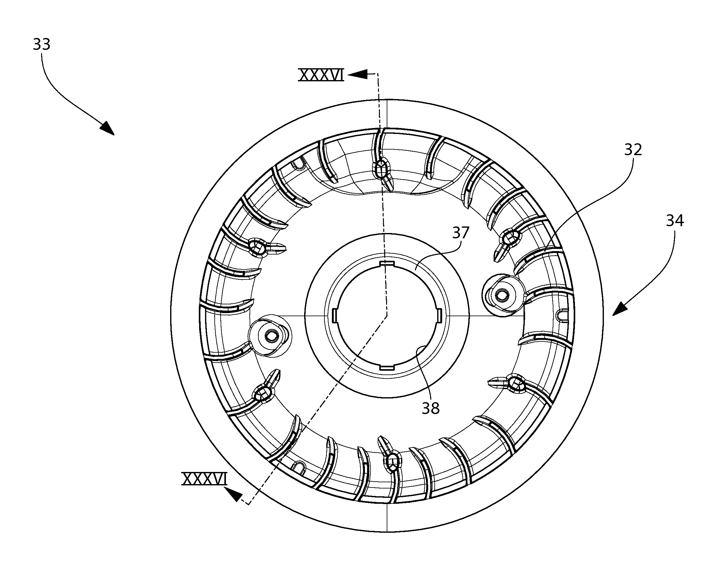
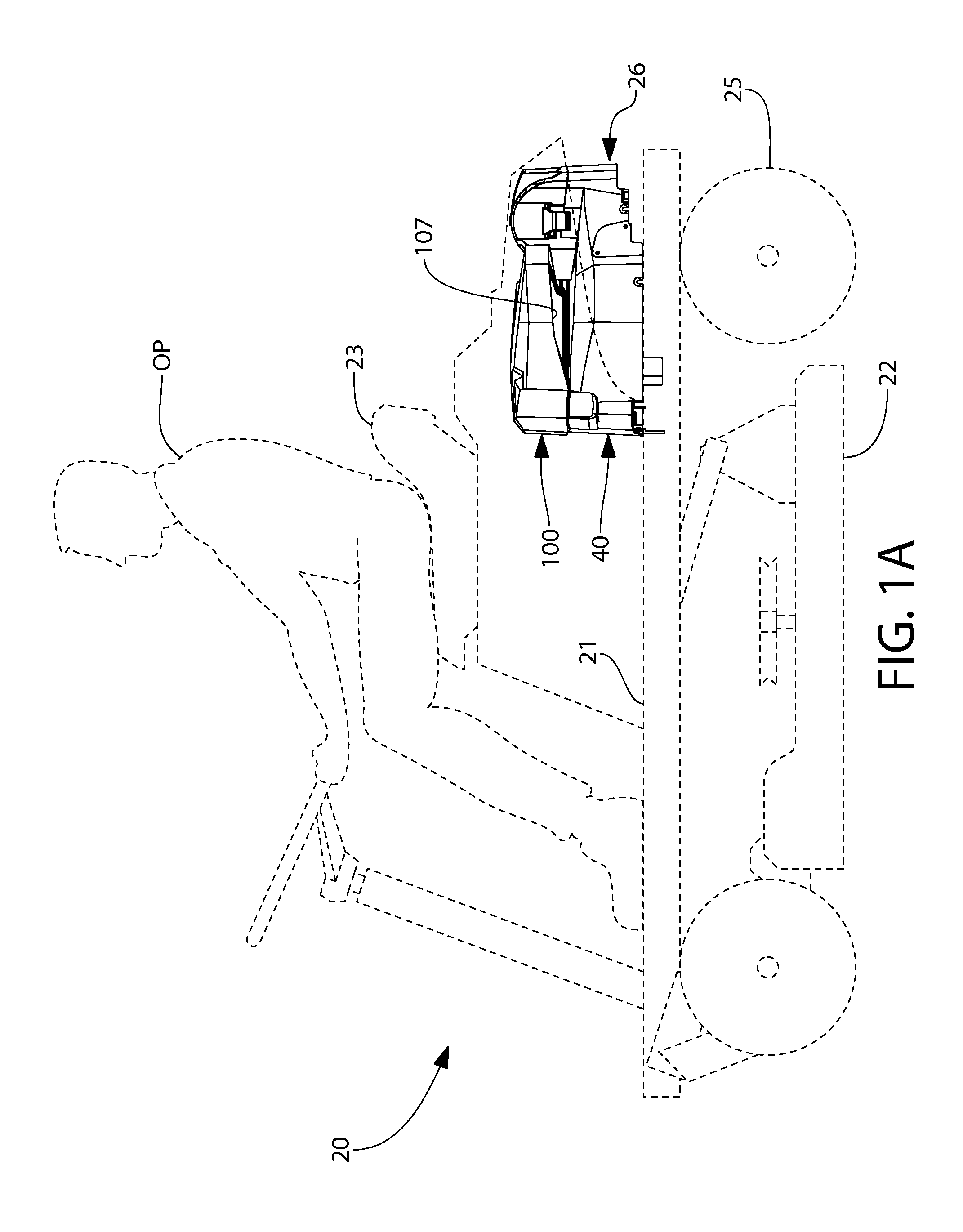
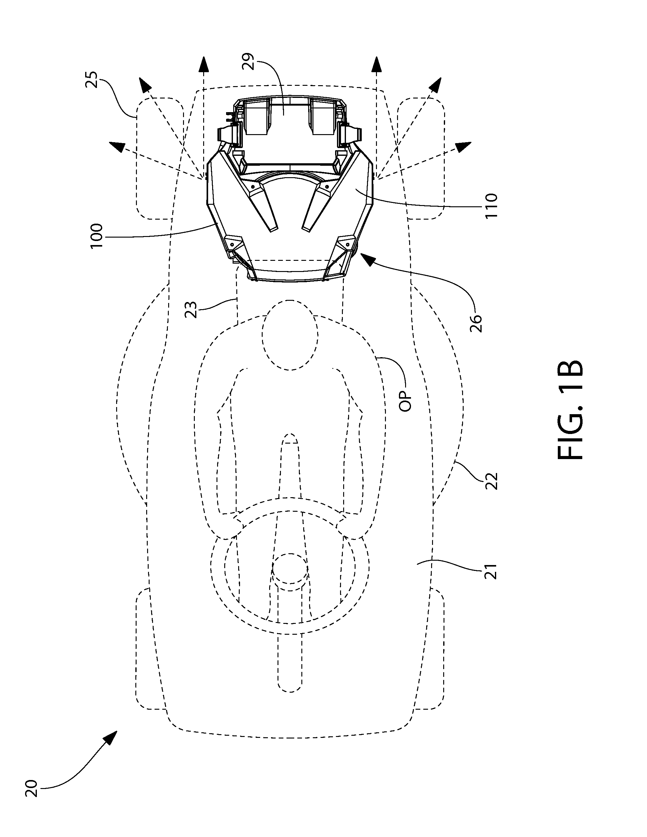
[0052]The features and benefits of the present disclosure are illustrated and described herein by reference to exemplary embodiments. This description of exemplary embodiments is intended to be read in connection with the accompanying drawings, which are to be considered part of the entire written description. Accordingly, the present disclosure expressly should not be limited to such embodiments illustrating some possible non-limiting combination of features that may exist alone or in other combinations of features; the scope of the claimed invention being defined by the claims appended hereto.

[0053]In the description of embodiments disclosed herein, any reference to direction or orientation is merely intended for convenience of description and is not intended in any way to limit the scope of the present invention. Relative terms such as “lower,”“upper,”“horizontal,”“vertical,”, “above,”“below,”“up,”“down,”“top” and “bottom” as well as derivative thereof (e.g., “horizontally,”“down...


PUM


Abstract

A noise suppression system for an air-cooled internal combustion engine is disclosed. The system may include an acoustically designed shroud forming a cavity and configured for attenuating noise produced by a cooling air fan associated with the engine. In one system, the shroud is mountable on a housing of the air fan. A pair of air inlet passages may be provided which are operable to draw ambient cooling air into the shroud to the fan. The air inlet passages are acoustically configured and tuned to attenuate noise generated by the fan. In one system, the air inlet passages may each be formed in a rear quadrant of the shroud. Various configurations of the shroud may include quarter wave resonators and / or micro-perforated panels to further attenuate fan noise.

Description

BACKGROUND OF THE INVENTION[0001]The present invention generally relates to sound or noise suppression, and more particularly to attenuate cooling system noise pertaining to air cooled internal combustion engines.[0002]Air cooled internal combustion engines are used to power outdoor equipment for a variety of applications including riding mowers, tractors, and others. Fans (sometimes referred to as “blowers”) used in engine cooling systems may be a source of noise.[0003]A noise suppression system for an engine is desirable.SUMMARY OF THE INVENTION[0004]A noise suppression system for an air cooled engine is disclosed that attenuates noise generated by operation of the engine's cooling fan or blower. In one aspect of the disclosure, the noise suppression system includes an acoustically designed shroud which in one configuration may be mounted on an air blower housing. The shroud may further be configured to define a cooling air inflow path for drawing ambient cooling air inwards towar...

Claims


Application Information

Patent Timeline
Patent Type & Authority Applications(United States)
IPC IPC(8): F01P11/12
CPCF01P11/12F04D29/665A01D34/826F01P5/02F01P5/06F02F1/065F04D17/16F04D29/4213F04D29/4226F04D29/424F04D29/582
Inventor LE ROY, TYLER W.BYKOWSKI, JONATHAN T.ALBERT, ROGER W.
Owner KOHLER CO
Learn More