Pixel shader bypass for low power graphics rendering

a graphics rendering and shader technology, applied in the field of three-dimensional graphics processing pipelines, can solve the problems of wasting processing power in certain graphics processing pipelines, two-dimensional blitter bypassing much or all and certain facilities of the graphics processing pipelin

Active Publication Date: 2014-09-18
NVIDIA CORP
View PDF4 Cites 25 Cited by
  • Summary
  • Abstract
  • Description
  • Claims
  • Application Information

AI Technical Summary

Problems solved by technology

One drawback of such an approach is that certain facilities of the graphics processing pipeline usually are not needed for drawing simple two-dimensional objects.
Consequently, having the graphics processing pipeline generate two-dimensional objects wastes processing power.
One drawback of such an approach is that the two-dimensional blitter usually bypasses much or all of the graphics processing pipeline.
Another drawback of using a two-dimensional blitter is that coordinating operations between the two-dimensional blitter and the graphics processing pipeline is difficult, which may result in the graphics processing pipeline being idled and flushed in order to operate the two-dimensional blitter, thereby reducing performance.

Method used


Image

  • Pixel shader bypass for low power graphics rendering
  • Pixel shader bypass for low power graphics rendering
  • Pixel shader bypass for low power graphics rendering

Examples


Embodiment Construction

[0021]In the following description, numerous specific details are set forth to provide a more thorough understanding of the present invention. However, it will be apparent to one of skill in the art that the present invention may be practiced without one or more of these specific details.

System Overview

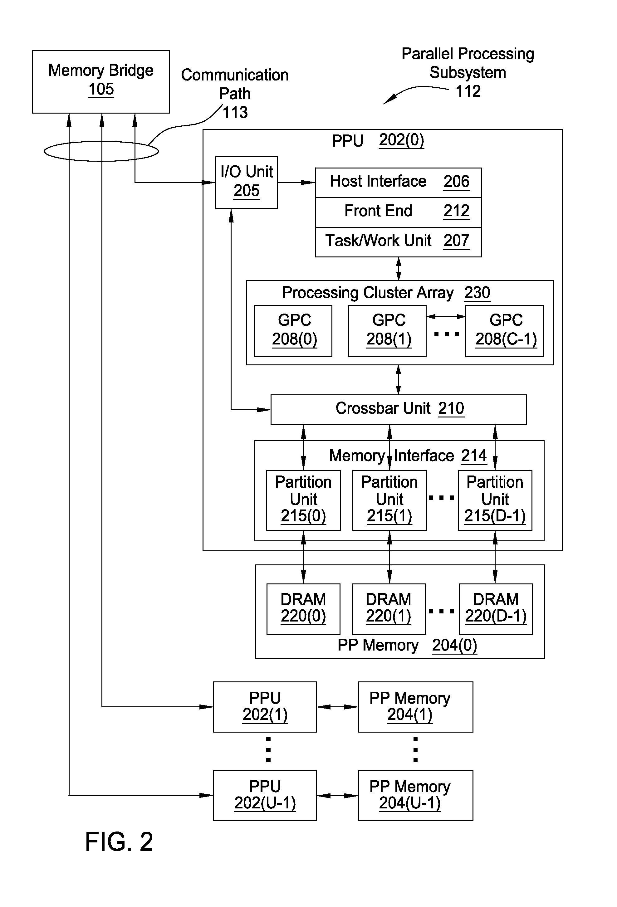
[0022]FIG. 1 is a block diagram illustrating a computer system 100 configured to implement one or more aspects of the present invention. Computer system 100 includes a central processing unit (CPU) 102 and a system memory 104 communicating via an interconnection path that may include a memory bridge 105. Memory bridge 105, which may be, e.g., a Northbridge chip, is connected via a bus or other communication path 106 (e.g., a HyperTransport link) to an I / O (input / output) bridge 107. I / O bridge 107, which may be, e.g., a Southbridge chip, receives user input from one or more user input devices 108 (e.g., keyboard, mouse) and forwards the input to CPU 102 via communication path 106 and m...


PUM


Abstract

A computer-implemented method for drawing graphical objects within a graphics processing pipeline is disclosed. The method includes determining that a bypass mode for a first primitive is a no-bypass mode. The method further includes rasterizing the first primitive to generate a first set of rasterization results. The method further includes generating a first set of colors for the first set of rasterization results via a pixel shader unit. The method further includes rasterizing a second primitive to generate a second set of rasterization results. The method further includes generating a second set of colors for the second set of rasterization results without the pixel shader unit performing any processing operations on the second set of rasterization results. The method further includes transmitting the first set of pixel colors and the second set of pixel colors to a raster operations (ROP) unit for further processing.

Description

BACKGROUND OF THE INVENTION[0001]1. Field of the Invention[0002]Embodiments of the present invention relate generally to three-dimensional graphics processing pipelines and, more specifically, to a pixel shader bypass for low power graphics rendering.[0003]2. Description of the Related Art[0004]An application may sometimes issue commands to draw two-dimensional objects within a three-dimensional scene that is being rendered via a graphics processing pipeline. For example, an application may request that a graphics processing pipeline render constant color two-dimensional or textured two-dimensional polygons in order to display user interface elements or to display simple graphical elements within a three-dimensional rendered scene. There are several ways that graphics processing pipelines can display such two-dimensional objects.[0005]In one approach, the application sends a command into the graphics processing pipeline to draw a polygon within the three-dimensional scene having spe...

Claims


Application Information

Patent Timeline
Patent Type & Authority Applications(United States)
IPC IPC(8): G06T1/20
CPCG06T1/20G06T11/40G06T15/005
Inventor LUM, ERIC B.COBB, JUSTINBASTOS, RUI M.ROUET, CHRISTIAN
Owner NVIDIA CORP
Why Eureka
Try Eureka