Apparatus and method for detecting position
a technology of apparatus and position, applied in the field of apparatus and method for detecting position, to achieve the effect of accurately detecting the position of a stylus pen
- Summary
- Abstract
- Description
- Claims
- Application Information
AI Technical Summary
Benefits of technology
Problems solved by technology
Method used
Image
Examples
first embodiment
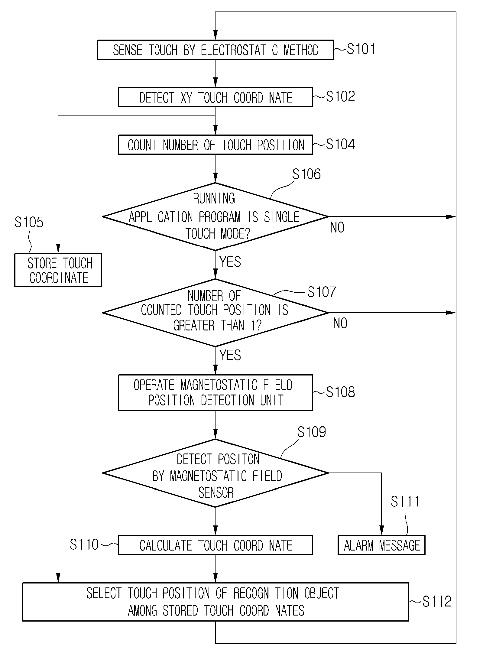
[0058]A position detection method by using the position detection apparatus according to an embodiment including the above-described components will be described. FIG. 7 is a flowchart illustrating a position detection method according to a
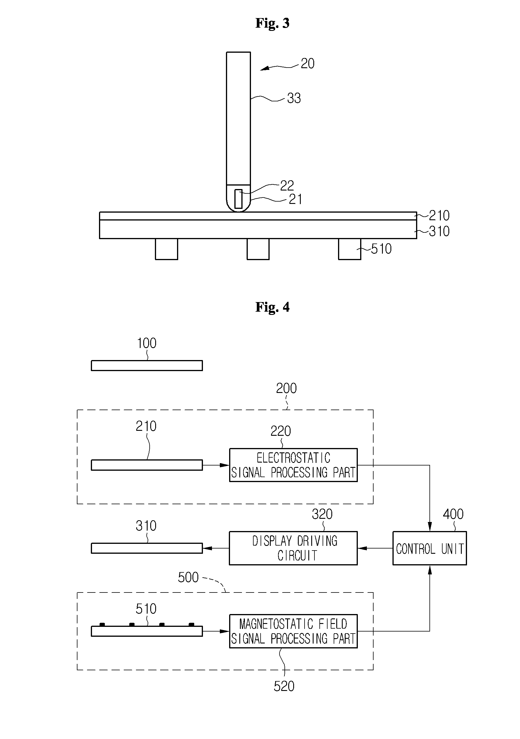
[0059]When a user' finger or pen touches a touch panel, the touch position is sensed by an electrostatic type position detection unit 200 (S101). That is, a signal is successively applied to capacitive pixels disposed in a matrix form in the touch panel to detect whether touch occurs or not into an electrical signal.
[0060]Also, a touch position is calculated based on a difference between the electrical signals of the pixels (e.g., between a driving electrode and a sensing electrode) in the touch panel (S102). The operations S101 and S102 are separately performed to easily express a sequence. However, the above-described two processes may be performed at a high speed or almost simultaneously. The electrostatic type position detection may be perform...
second embodiment
[0074]FIG. 8 is a flowchart illustrating a position detection method according to a When a user's finger or pen touches a touch panel, the touch position is sensed by an electrostatic type position detection unit 200 (S201). That is, a signal is successively applied to capacitive pixels disposed in a matrix form in the touch panel to detect whether touch occurs or not into an electrical signal.
[0075]Also, a touch position is calculated on the basis of a difference between the electrical signals of the pixels (e.g., between a driving electrode and a sensing electrode) in the touch panel (S202). The operations S201 and S202 are separately performed to easily express a sequence. However, the above-described two processes may be performed at a high speed or almost simultaneously. The electrostatic type position detection may be performed through the well-known methods. However, at least one portion of an outer surface of the pen according to an embodiment may be formed of a material in...
third embodiment
[0119]FIG. 16 is a view illustrating an inner structure of a pen according to a A magnet 822 disposed inside a head part 821 of a pen is connected to a magnet connection member 825. The magnet connection member 825 is connected to a spring connection member 826 fixed to a first spring 840. Also, the spring connection member 826 is connected to a protrusion connection member 828 disposed above the spring connection member 826.
[0120]The first spring 840 is disposed under the spring connection member 826. Also, the first spring 840 has one end fixed to the spring connection member 826 and the other end fixed to a predetermined portion of a body part 823. Also, the spring fixed to the spring connection member 826 may be provided in plurality. As shown in FIG. 16, the springs may be disposed on both sides with respect to a center of the magnet connection member 825.
[0121]In this structure, when the protrusion connection member 828 ascends in position, the spring connection member 826 an...
PUM
 Abstract
Description
Claims
Application Information
 - R&D
- Intellectual Property
- Life Sciences
- Materials
- Tech Scout
- Unparalleled Data Quality
- Higher Quality Content
- 60% Fewer Hallucinations
Browse by: Latest US Patents, China's latest patents, Technical Efficacy Thesaurus, Application Domain, Technology Topic, Popular Technical Reports.
© 2025 PatSnap. All rights reserved.Legal|Privacy policy|Modern Slavery Act Transparency Statement|Sitemap|About US| Contact US: help@patsnap.com


