Negative capacitance circuit, resonance circuit and oscillator circuit

a negative capacitance circuit and resonance circuit technology, applied in the direction of oscillator generators, network simulating negative resistances, electrical apparatus, etc., can solve the problems of insufficient inductance value adjustment, inability to cancel temperature change to obtain stable oscillation frequency, disadvantageous inductance value significant change,

Inactive Publication Date: 2014-09-18
NIHON DEMPA KOGYO CO LTD
View PDF0 Cites 5 Cited by
  • Summary
  • Abstract
  • Description
  • Claims
  • Application Information

AI Technical Summary

Problems solved by technology

Accordingly, in an oscillator circuit using the MEMS resonator, it is difficult to cancel the temperature change to obtain a stable oscillation frequency only by adjusting the bias voltage.
An inductor disadvantageously changes its inductance value significantly in response to temperature change.
Also, it is difficult to adjust an inductance value in response to the variation of a resonator.
Accordingly, a resonance circuit using an inductor cannot obtain an oscillation signal having a stable oscillation frequency.
Furthermore, it is difficult to incorporate an inductor having an inductance value on the order of μH into an integrated circuit.
Consequently, it is impossible to achieve the low cost mass production of oscillator circuits that can obtain an oscillation signal having a stable oscillation frequency using the conventional anti-resonance circuit 400.
On the other hand, as disclosed in Japanese Unexamined Patent Application Publication Nos. 2002-124713 and H08-204451, in the case where an negative capacitance circuit is configured by using an operational amplifier as an active element, the oscillation frequency of the oscillator circuit to which the negative capacitance circuit can be connected is disadvantageously limited to the extent of several MHz since the operation bandwidth of the operational amplifier is not sufficiently large.
S60-157317, International Publication Number WO 00 / 04647, and U.S. Pat. No. 7,609,111, in the case where a negative capacitance circuit is configured by combining a plurality of transistors, an undesired oscillation is unfortunately caused easily.
In addition, a conventional negative capacitance circuit has a return gain S11 at high frequencies, so that when the negative capacitance circuit is connected to another circuit, an undesired oscillation is sometimes caused.

Method used


Image

  • Negative capacitance circuit, resonance circuit and oscillator circuit
  • Negative capacitance circuit, resonance circuit and oscillator circuit
  • Negative capacitance circuit, resonance circuit and oscillator circuit

Examples


first embodiment

Effect of First Embodiment

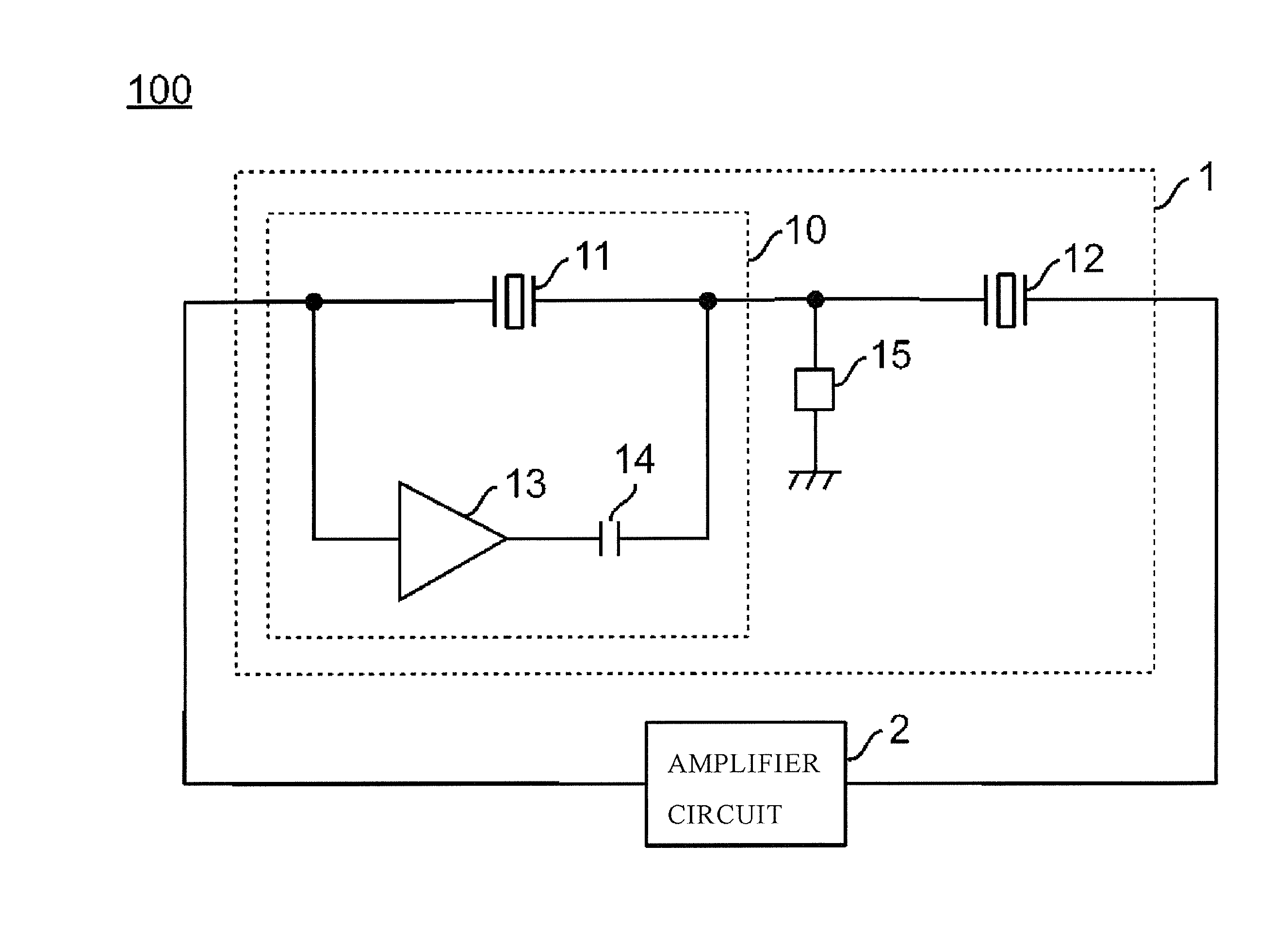
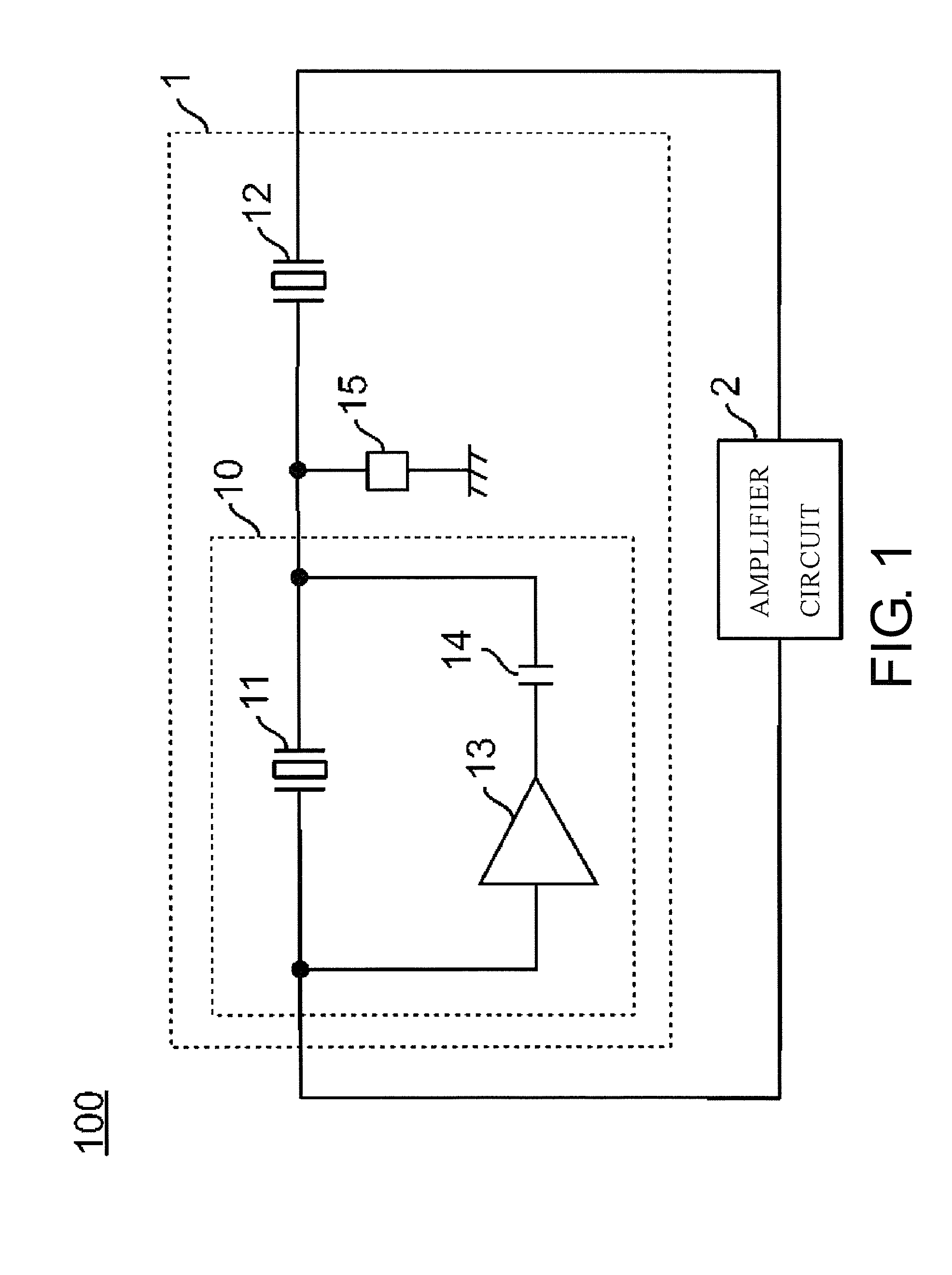
[0055]As described above, the resonance circuit 1 according to the first embodiment includes the first resonator 11, the second resonator 12, the inverting amplifier 13, the capacitance element 14, and the negative capacitance circuit 15. The second resonator 12 is connected to the resonance circuit 1 in series. The inverting amplifier 13 and the capacitance element 14 are connected to the first resonator 11 in parallel, and are connected each other in series. The negative capacitance circuit 15 is disposed between the node between the first resonator 11 and the second resonator 12, and ground. Accordingly, a resonance frequency can be set between the resonance frequency fr1 of the first resonator 11 and the resonance frequency fr2 of the second resonator 12.

Connecting Variable Resistors to Resonators in Parallel of Second Embodiment

[0056]FIG. 4 illustrates an exemplary configuration of a resonance circuit 1 according to a second embodiment. The resonance c...

second embodiment

Effect of Second Embodiment

[0061]As described above, the resonance circuit 1 according to the second embodiment further includes the first variable resistor 18 and second variable resistor 19. Accordingly, the resonance circuit 1 can adjust the resonance frequency of the resonance circuit 1 between the resonance frequency of the first resonator 11 and the resonance frequency of the second resonator 12. Namely, the resonance circuit 1 according to the second embodiment can change the peak frequency in the frequency characteristic of the resonance circuit 1 illustrated by the solid line in FIG. 3A between the resonance frequency fr1 of the first resonator 11 and the resonance frequency fr2 of the second resonator 12 in response to the resistance values of the first variable resistor 18 and second variable resistor 19.

Third embodiment

Variable Capacitance Element Between the First Resonator 11 and the Second Resonator 12

[0062]FIG. 5 illustrates an exemplary configuration of the resonanc...

third embodiment

Effect of Third Embodiment

[0066]As described above, the resonance circuit 1 according to the third embodiment further includes the variable capacitance element 20. Accordingly, the resonance frequency of the resonance circuit 1 can vary more freely.


PUM


Abstract

A resonance circuit includes a first resonator, a second resonator, a capacitance element and an inverting amplifier, and a negative capacitance circuit. The second resonator is connected to the first resonator in series. The capacitance element and the inverting amplifier are connected to one another in series. The capacitance element and the inverting amplifier are connected to the first resonator in parallel. The negative capacitance circuit is connected between a node and ground. The node is disposed between the first resonator and the second resonator.

Description

CROSS-REFERENCE TO RELATED APPLICATIONS[0001]This application claims the priority benefit of Japan application serial Nos. 2013-049253 and 2013-049254, filed on Mar. 12, 2013 and Nos. 2014-027158 and 2014-027159, filed on Feb. 17, 2014. The entirety of each of the above-mentioned patent applications is hereby incorporated by reference herein and made a part of this specification.TECHNICAL FIELD[0002]This disclosure relates to a negative capacitance circuit, a resonance circuit and an oscillator circuit.DESCRIPTION OF THE RELATED ART[0003]An anti-resonance circuit is conventionally known, which can adjust an oscillation frequency in a frequency range wider than a frequency range adjustable by a single crystal resonator by using more than one crystal resonators whose resonance frequencies are different from each other (for example, see Japanese Unexamined Patent Application Publication No. 2007-295256 (hereinafter referred to as Patent Literature 1)).[0004]FIG. 17 illustrates an exemp...

Claims


Application Information

Patent Timeline
Patent Type & Authority Applications(United States)
IPC IPC(8): H03B5/30H03H11/52
CPCH03H11/52H03B5/30H03H11/481H03B5/362H03B5/368H03B2201/02H03B2201/0208H03H11/48
Inventor ISHII, TAKEHITO
Owner NIHON DEMPA KOGYO CO LTD
Why Eureka
Try Eureka