
Methods And Systems For Improving The Operation Of Transmissions For Motor Vehicles

a transmission and motor vehicle technology, applied in the direction of fluid pressure control, process and machine control, instruments, etc., can solve the problems of converter drain-back, delay (or no engagement), pump noise, operation failure, etc., to reduce the possibility of leakage, and distribute wear evenly

Inactive Publication Date: 2014-09-18
SILENT PARTNER GRANTS
View PDF4 Cites 2 Cited by
  • Summary
  • Abstract
  • Description
  • Claims
  • Application Information

AI Technical Summary

Benefits of technology

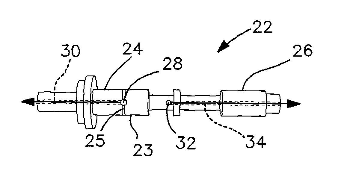
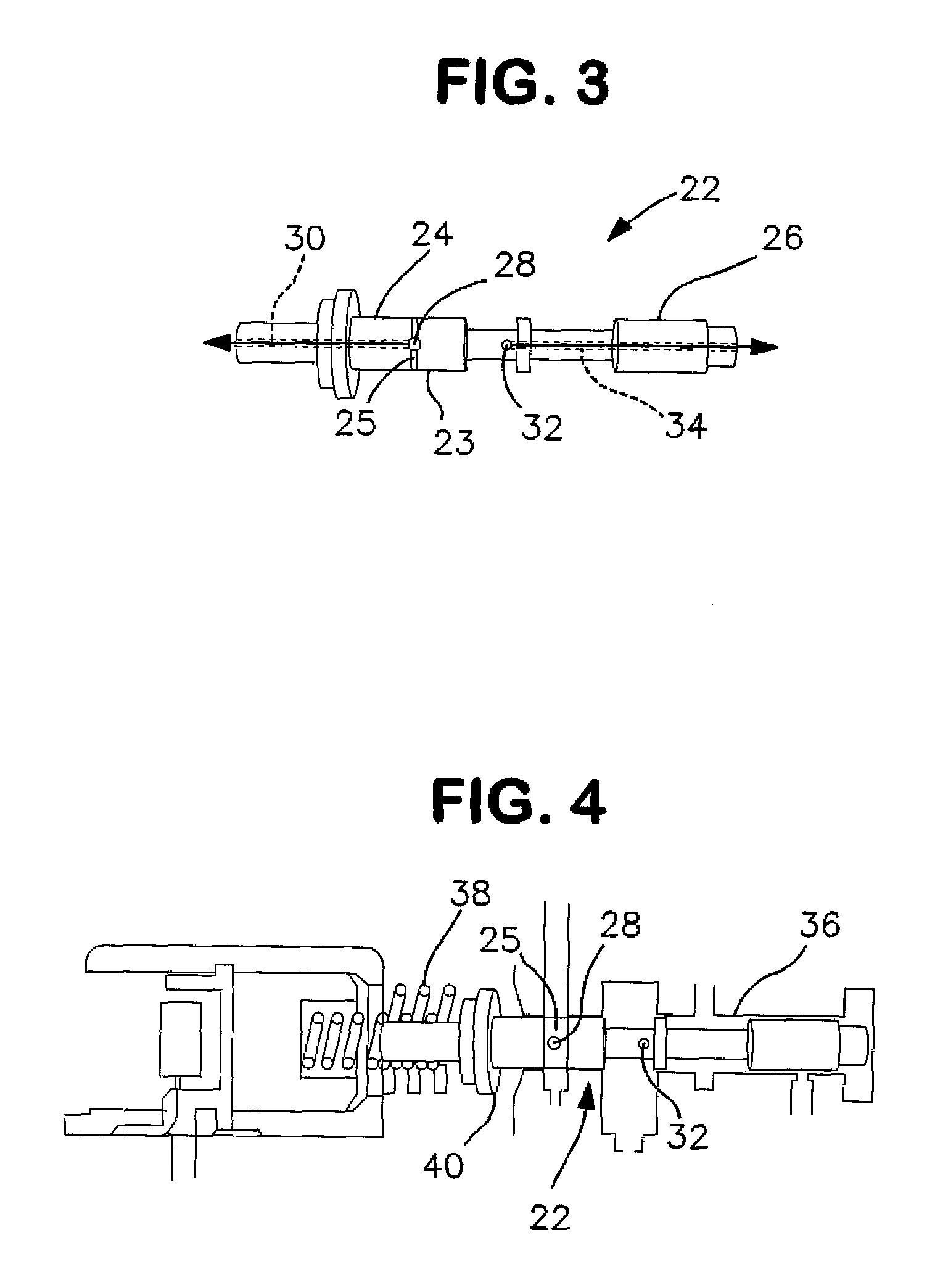
The present invention is a modification to the pressure regulator valve in an automotive transmission. By relocating the pressure regulator balance circuit and / or the decrease exhaust circuit internally with the valve, the width of the inner and outer lands of the valve can be increased, which increases surface area in contact with the valve bore, resulting in a more firm seal between the valve and the bore. This modification improves the operational life of the pressure regulator valve and the pressure regulator circuit, avoiding leaks and failures, and reducing the need for costly and unnecessary replacements and repairs to correct failures of the original transmission. In summary, the modification improves the reliability, efficiency, and useful operating life of the automotive transmission.

Problems solved by technology

The present inventor has recognized that the main pressure regulator bore in the aforementioned “factory installed” GM automotive transmissions can suffer damage from use over time, resulting in wear causing a variety of operational failures including loss of pump pressure control, converter drain-back, delayed (or no) engagement, pump noise and catastrophic drum breakage.
Known solutions to these conditions are expensive and require either a complete replacement of components, or purchasing specialized and expensive boring tools and additional holding fixtures to re-bore half of the fluid pump and thereafter purchasing and installing oversized valves.

Method used


Image

  • Methods And Systems For Improving The Operation Of Transmissions For Motor Vehicles
  • Methods And Systems For Improving The Operation Of Transmissions For Motor Vehicles
  • Methods And Systems For Improving The Operation Of Transmissions For Motor Vehicles

Examples


Embodiment Construction

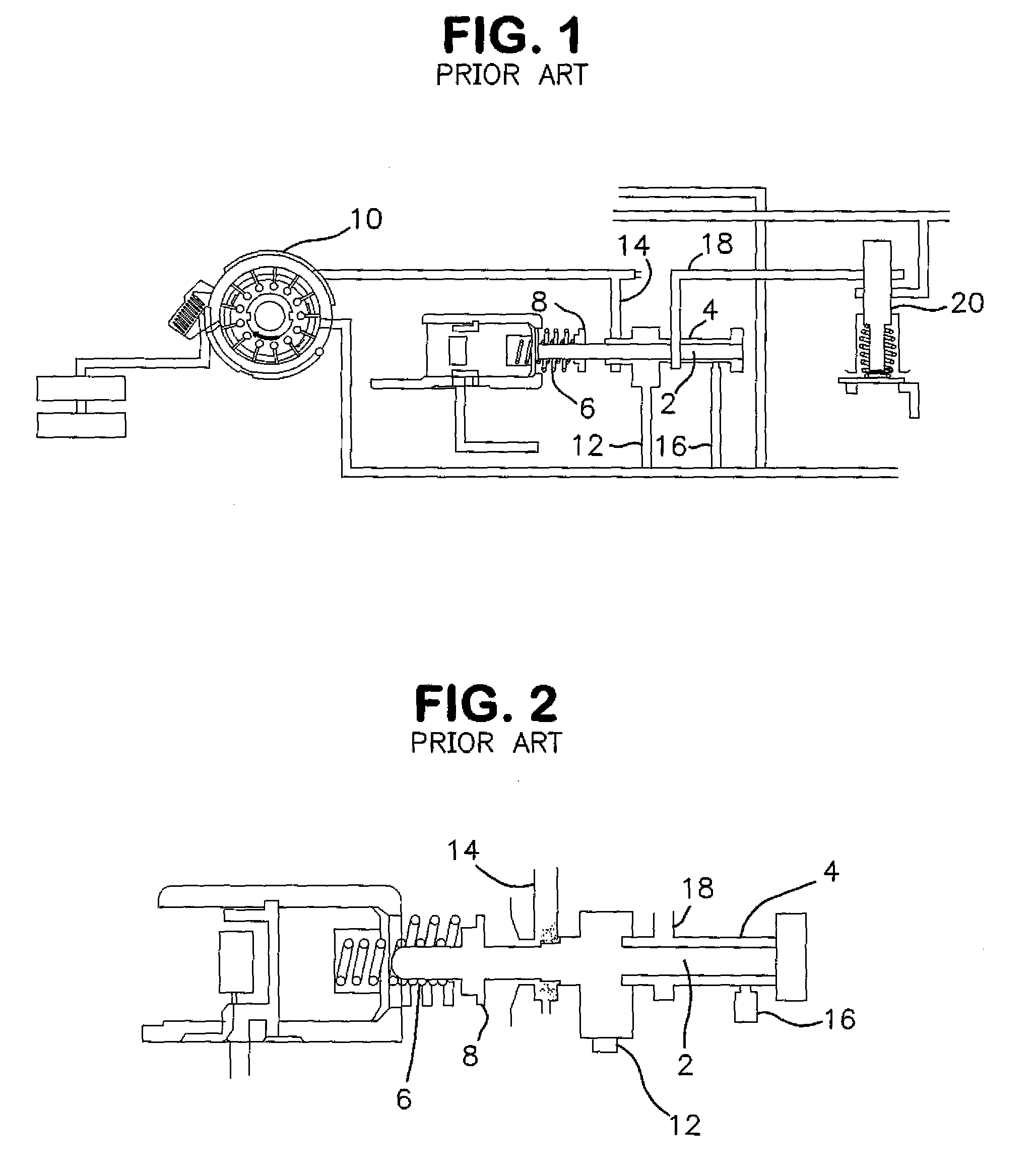
[0019]FIGS. 1-3 illustrate the hydraulic circuitry of a known “factory installed” automotive transmissions designated as 6L80E, 6L85E, 6L90E, 5L40E, 4L60E, 4L65E, and 4L70E, installed in motor vehicles manufactured by General Motors Corporation.

[0020]FIG. 1 illustrates the pressure regulator circuit of the aforementioned “factory installed” automotive transmissions. A pressure regulator valve designated by reference numeral 2 is moveable within a bore designated by reference numeral 4, and a spring designated by reference numeral 6 exerts a resilient force on a spring seat designated by reference numeral 8 on the pressure regulator valve. A fluid pump designated by reference numeral 10 is in fluid communication with the pressure regulator valve through a line designated by reference numeral 12. A decrease exhaust circuit is provided by a line 14 also in fluid communication with the pressure regulator valve. A line 16 provides fluid communication between the pressure regulator valve ...


PUM


Abstract

A pressure regulator valve to replace the pressure regulator valve of a “factory installed” automotive transmission has a pressure regulator balance circuit provided internally within a first portion of the pressure regulator valve. The pressure regulator valve also has a decrease exhaust circuit provided internally within a second portion of the pressure regulator valve. One or more outer lands of the pressure regulator valve has a width greater than that of the outer land of the “factory installed” pressure regulator valve, and the pressure regulator valve has an inner land having a greater width than that of the inner land of the “factory installed” pressure regulator valve. The pressure regulator valve provides efficient pump control while providing support and stability greater than that provided by the “factory installed” pressure regulator valve.

Description

[0001]The present patent application claims the benefit of U.S. Provisional Patent Application Ser. No. 61 / 851,763 filed on Mar. 13, 2013, pursuant to 35 U.S.C. 119 (e).BACKGROUND OF THE INVENTION[0002]The methods and systems of the present invention are directed to the modification and improvement of transmissions for automotive vehicles, more commonly referred to as “factory installed” transmissions, installed in automotive vehicles by an original motor vehicle manufacturer. The present invention is more particularly directed to improvements to the “factory installed” transmissions for General Motors Corporation (GM) vehicles equipped with automatic transmissions identified as 6L80E, 6L85E, 6L90E, 5L40E, 4L60E, 4L65E, and 4L70E.[0003]The present inventor is the inventor identified in the following United States patents and published patent application, the disclosures of which are expressly incorporated by reference into the present patent application: U.S. Pat. No. 4,449,426, iss...

Claims


Application Information

Patent Timeline
Patent Type & Authority Applications(United States)
IPC IPC(8): F16K51/00
CPCF16K51/00F16K11/0716F16H2061/0062F16H61/0021G05D16/101Y10T137/7758Y10T137/0491
Inventor YOUNGER, GILBERT W.
Owner SILENT PARTNER GRANTS
Learn More