Dual chamber liquid packaging system
a liquid packaging and dual chamber technology, applied in fluid controllers, laboratory glassware, chemistry apparatus and processes, etc., can solve the problems of inactive or useless liquid reagents for clinical use, increased processing time, and increased costs for developing nations, and achieve the effect of enhancing the piercing ability of the piercing member
- Summary
- Abstract
- Description
- Claims
- Application Information
AI Technical Summary
Benefits of technology
Problems solved by technology
Method used
Image


Examples
embodiment 1
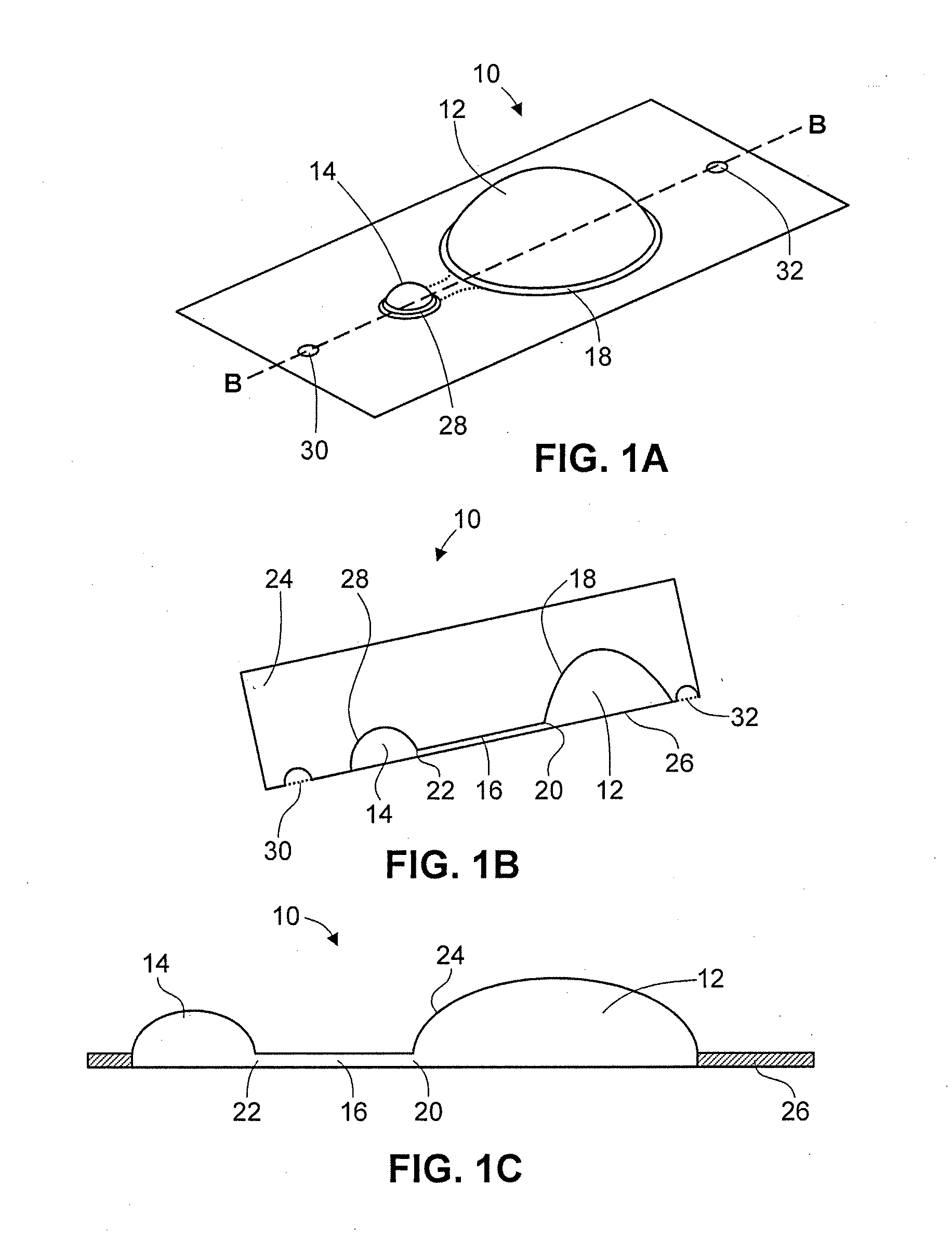
2. The system of embodiment 1, wherein the primary chamber has a larger volume than the secondary chamber.
3. The system of the separate or combined embodiments 1-2, wherein the upper layer of the secondary chamber is of a material that is more ductile than the material of the lower layer.
4. The system of the separate or combined embodiments 1-3, wherein the material of the lower layer is a foil.
5. The system of the separate or combined embodiments 1-4, wherein the material of the upper layer and / or the material of the lower layer is a laminate.
6. The system of the separate or combined embodiments 1-5, wherein the primary chamber is comprised of an upper layer and a lower layer joined about a perimeter of the chamber other than at a junction of the channel and the primary chamber.
7. The system of the separate or combined embodiments 1-6, wherein the upper layer and lower layer of the secondary chamber are joined about a perimeter of the chamber other than at a junction of the channel...
embodiment 15
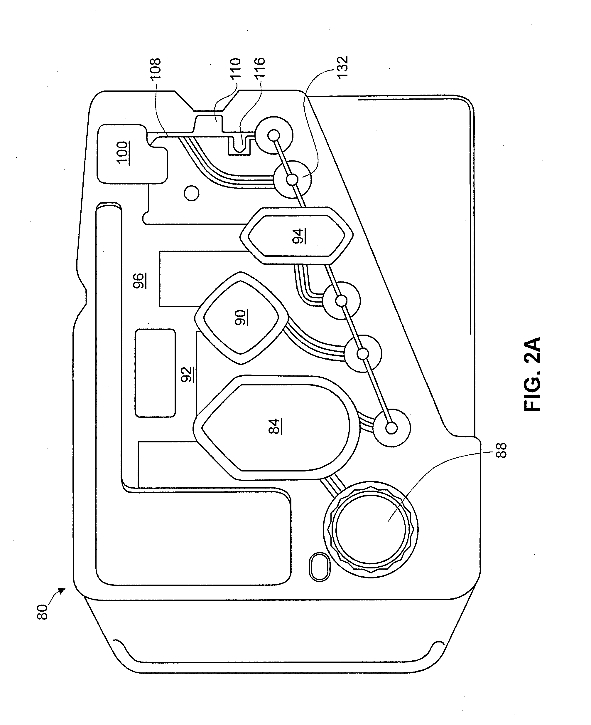
16. The device of embodiment 15, wherein the planar cartridge further comprises an inlet port associated with the reaction chamber, and wherein the secondary chamber of the packaging member is aligned with the inlet port such that when the lower layer opens the fluid is dispensed from the packaging member into the reaction chamber via the inlet port.
17. The device of the separate or combined embodiments 15-16, wherein the planar cartridge comprises a plurality of reaction chambers, each reaction chamber having an inlet port, and wherein the backing member comprises a plurality of packaging members.
18. The device of the separate or combined embodiments 15-17, wherein the number of packaging members in the plurality is the same as or exceeds the number of reaction chambers in the planar cartridge.
19. The device of the separate or combined embodiments 15-18, wherein the primary chamber of the liquid packaging member contains a fluid selected from the group consisting of a water-immisci...
embodiment 27
28. The system of embodiment 27, wherein the planar cartridge further comprises an inlet port and a reaction chamber, wherein the inlet port is associated with the reaction chamber, and wherein the secondary chamber of the packaging member is aligned with the inlet port such that when the lower layer opens the fluid is dispensed from the packaging member into the reaction chamber via the inlet port.
29. The system of the separate or combined embodiments 27-28, wherein the planar cartridge comprises a plurality of reaction chambers, each reaction chamber having an inlet port, and wherein the backing member comprises a plurality of packaging members.
30. The system of the separate or combined embodiments 27-29, wherein each inlet port includes a piercing member for piercing the lower layer of the associated secondary chamber.
31. The system of the separate or combined embodiments 27-30, wherein at least one of the piercing member and the secondary chamber is movable by an externally appl...
PUM
 Abstract
Description
Claims
Application Information
 - R&D
- Intellectual Property
- Life Sciences
- Materials
- Tech Scout
- Unparalleled Data Quality
- Higher Quality Content
- 60% Fewer Hallucinations
Browse by: Latest US Patents, China's latest patents, Technical Efficacy Thesaurus, Application Domain, Technology Topic, Popular Technical Reports.
© 2025 PatSnap. All rights reserved.Legal|Privacy policy|Modern Slavery Act Transparency Statement|Sitemap|About US| Contact US: help@patsnap.com