Geosynthetic Composite for Filtration and Drainage of Fine-Grained Geomaterials

Active Publication Date: 2014-09-11
GSE ENVIRONMENTAL
View PDF6 Cites 9 Cited by
  • Summary
  • Abstract
  • Description
  • Claims
  • Application Information

AI Technical Summary

Benefits of technology

The present invention provides a geotechnical construction site with a geotextile filter and a geonet. The geotextile is made up of a nonwoven fabric and a woven fabric, with the nonwoven fabric having a larger opening size than the woven fabric. The nonwoven fabric is connected to the woven fabric by needle-punching, and the combined permeability of the two fabrics is greater than 0.1 cm / sec. The geotextile filter and geonet can be used to prevent contamination in construction projects. The invention also includes a landfill with alternating layers of fill and geocomposites to facilitate draining of liquid from the landfill. The geotextile is bonded to the geonet, which includes a plurality of connected strands. The nonwoven fabric has a cross-plane water flow rate of greater than 3,000 liter / min / m2. The woven fabric has a cross-plane water flow rate between about 500 and 8,000 liter / min / m2.

Problems solved by technology

Meeting such conflicting requirements can be, and has been, difficult for systems in which a very high content of fine-grained geomaterials is present.
Moreover, such fabrics can encounter serious filtration problems such as fines' migration (called “piping”) or filter clogging.
However, tensile strains on such nonwoven fabrics can change the pore opening sizes over the life of the product.
Moreover, manufacture of nonwoven fabrics will occasionally result in a fabric which has small light spots with larger openings than other areas of the fabric, and such spats will control the ultimate filtration performance of the material.
However, woven filters typically have only a limited number of the openings per unit area, and fines particles can accumulate at any individual opening and block the water flow (called “surface blinding”).
In short, such geotextile filters can encounter difficulty over their useful life, particularly in environments where high contents of fine-grained geomaterials are present.
As a result, it has been common in CCPs landfills to utilize a leachate collection system made of the costly and space-consuming granular materials (e.g., several feet of a fine sand filtration layer plus an aggregate or well-graded bottom ash drainage layer).

Method used


Image

  • Geosynthetic Composite for Filtration and Drainage of Fine-Grained Geomaterials
  • Geosynthetic Composite for Filtration and Drainage of Fine-Grained Geomaterials
  • Geosynthetic Composite for Filtration and Drainage of Fine-Grained Geomaterials

Examples


Embodiment Construction

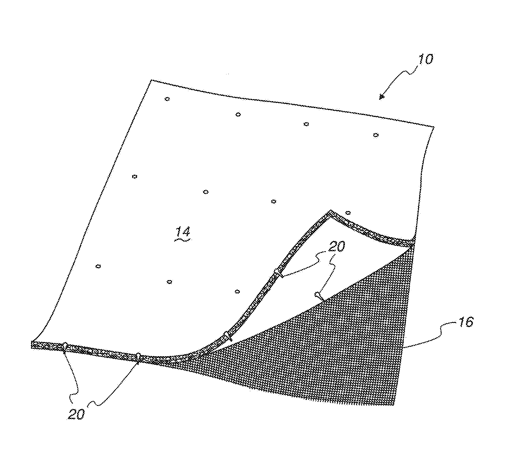
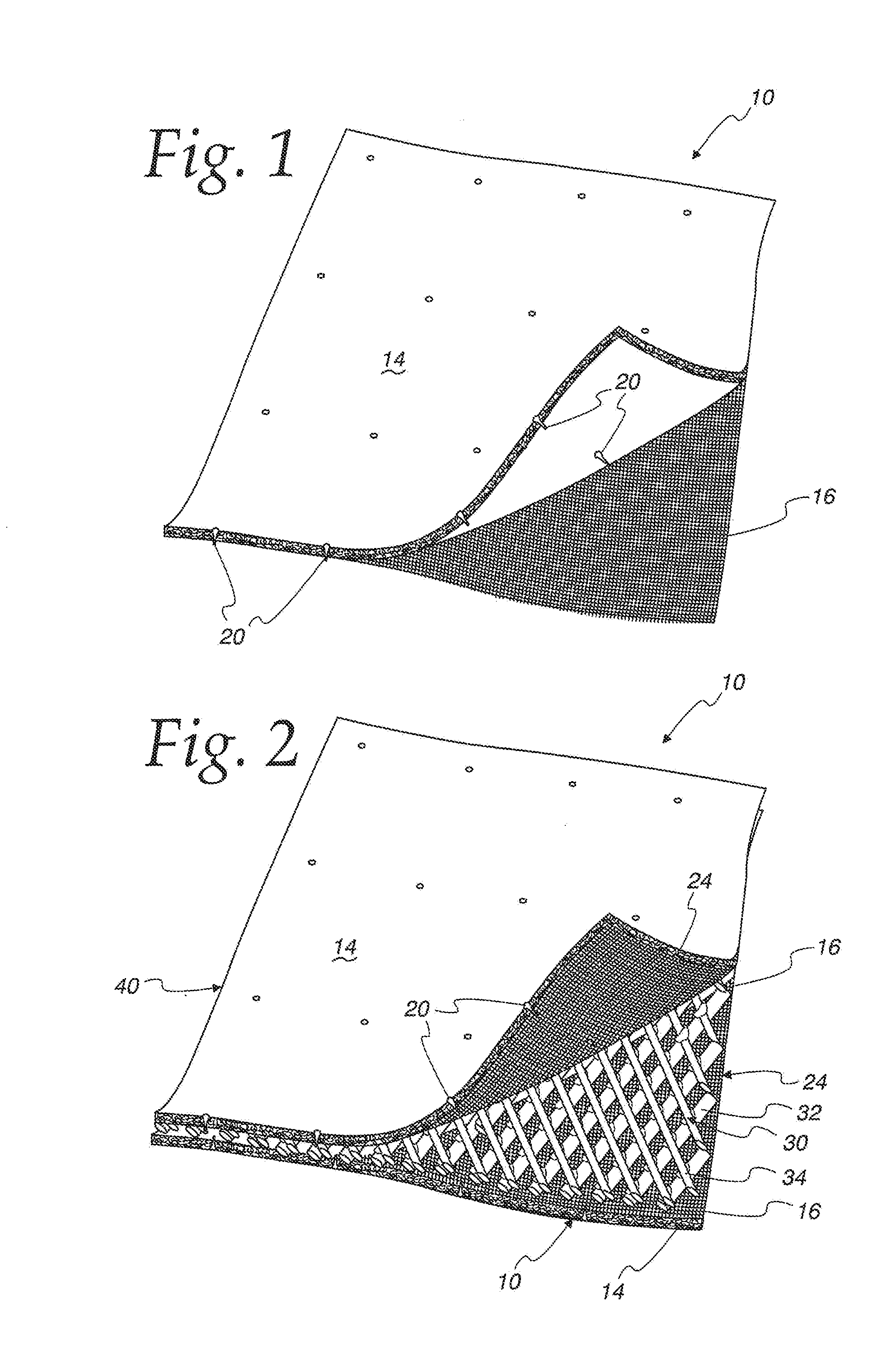
[0039]FIG. 1 illustrates a two-layer geotextile filter 10 having a primary filter layer 14 consisting of a nonwoven fabric and a secondary filter layer 16 consisting of a woven fabric. As described in further detail below, the two layers 14, 16 are needle-punched together to make an integral two-layer geotextile filter 10 wherein fibers 20 of the nonwoven fabric layer 14 project through the woven fabric layer 16 so as to form a fuzzy surface 24 on the side of the woven fabric layer 16 opposite of the nonwoven fabric layer 14 (as illustrated in FIGS. 1 and 2, only a few such fibers 20 are highlighted for clarity of the drawing).

[0040]The nonwoven primary filter layer 14 may be advantageously manufactured from needle-punching staple fibers, with the denier of the fibers and size of the needle selected to provide an opening size distribution that is needed for the target application. Thus, in accordance with the present invention, the primary filter layer 14 may advantageously have an ...


PUM

PropertyMeasurementUnit
Pressureaaaaaaaaaa
Lengthaaaaaaaaaa
Lengthaaaaaaaaaa

Abstract

A geocomposite with a geonet and a geotextile. The geotextile has a nonwoven fabric layer and a woven fabric layer, with the nonwoven fabric connected by needle-punching to the woven fabric whereby fibers of the nonwoven fabric extend through and beyond the woven fabric, and the woven fabric and fibers of the nonwoven fabric extending through the woven fabric are bonded to one side of the geonet.

Description

CROSS-REFERENCE TO RELATED APPLICATIONS[0001]Not Applicable.FEDERALLY SPONSORED RESEARCH OR DEVELOPMENT[0002]Not Applicable.MICROFICHE / COPYRIGHT REFERENCE[0003]Not Applicable.FIELD OF THE INVENTION[0004]The present invention is directed toward geocomposites, and more particularly toward geocomposites usable in environments in which high content of fine-grained geomaterials is presentBACKGROUND OF THE INVENTION[0005]Effective filtration and drainage systems has proven to be critical in geotechnical and geoenvironmental engineering of fine-grained geomaterials, such as silts or clays, coal combustion products (CCPs) including fly ash and flue gas clesuifurization (FGD) materials, and river or sea dredged sediments, etc. For instance, coal combustion products (CCPs) are regularly deposited in landfills which require a leachate collection system beneath the CCPs waste to provide sufficient drainage and reduce the hydraulic head on top of water-barrier liners.[0006]Leachate collection sy...

Claims


Application Information

Patent Timeline
IPC IPC(8): B01D39/08B09B1/00B32B37/14
CPCB01D39/08B32B37/14B09B1/00B32B37/0084B32B38/04B32B2038/042B32B2305/188B32B2305/20B01D39/083B01D2239/0659B01D39/1623B01D2239/0208B01D2239/0216B09B1/008B32B5/022B32B5/024B32B5/028B32B5/06B32B5/26B32B37/144B32B37/16B32B2262/0253B32B2262/0276B32B2307/726
Inventor LI, JR., MENGJIAHEATHCOTT, DARRELL L.
Owner GSE ENVIRONMENTAL
Why Eureka
Try Eureka