
Electrophotographic image forming apparatus

a technology of forming apparatus and electrophotography, which is applied in the direction of electrographic process apparatus, instruments, corona discharge, etc., can solve the problems of reducing the waiting time for users, reducing the power consumption, and complicating the efforts to shorten the first image output time. , to achieve the effect of shortening the first image output tim

Active Publication Date: 2014-09-11
RICOH KK
View PDF3 Cites 7 Cited by
  • Summary
  • Abstract
  • Description
  • Claims
  • Application Information

AI Technical Summary

Benefits of technology

The need for an image forming apparatus that can create images without uneven color or horizontal streaks while reducing the time it takes to output the first image is still unsolved.

Problems solved by technology

However, in order to reduce power consumption, in general, it is necessary to reduce the process linear velocity, thereby complicating efforts to shorten the first image output time as is usually desired.
In other words, efforts to shorten the first image output time contradict efforts to reduce the power consumption.
Therefore, shortening the preparation time for printing in the image forming unit can lead to reduction of the waiting time for the users, and hence there is demand for a short preparation time for printing.
Although advantageous, there is a relatively long time lag between the start of charging and the start of image formation, resulting in a relatively long first image output time (FCOT).
With this configuration, the trace of the transfer bias does not remain, and writing can be started when the leading end of the charged portion of the surface 102a arrives at the writing position C. However, providing the charge removing device to remove the charge on the surface 102a over the entire axial direction of the photosensitive drum 102 is expensive.
Thus, the density difference is difficult to occur.
However, the image forming apparatus proposed in JP-2010-26083-A does not specify the timing at which the primary transfer bias is supplied.

Method used


Image

  • Electrophotographic image forming apparatus
  • Electrophotographic image forming apparatus
  • Electrophotographic image forming apparatus

Examples


Embodiment Construction

[0046]A description is now given of illustrative embodiments of the present invention. It should be noted that although such terms as first, second, etc. may be used herein to describe various elements, components, regions, layers and / or sections, it should be understood that such elements, components, regions, layers and / or sections are not limited thereby because such terms are relative, that is, used only to distinguish one element, component, region, layer or section from another region, layer or section. Thus, for example, a first element, component, region, layer or section discussed below could be termed a second element, component, region, layer or section without departing from the teachings of this disclosure.

[0047]In addition, it should be noted that the terminology used herein is for the purpose of describing particular embodiments only and is not intended to be limiting of this disclosure. Thus, for example, as used herein, the singular forms “a”, “an” and “the” are int...


PUM


Abstract

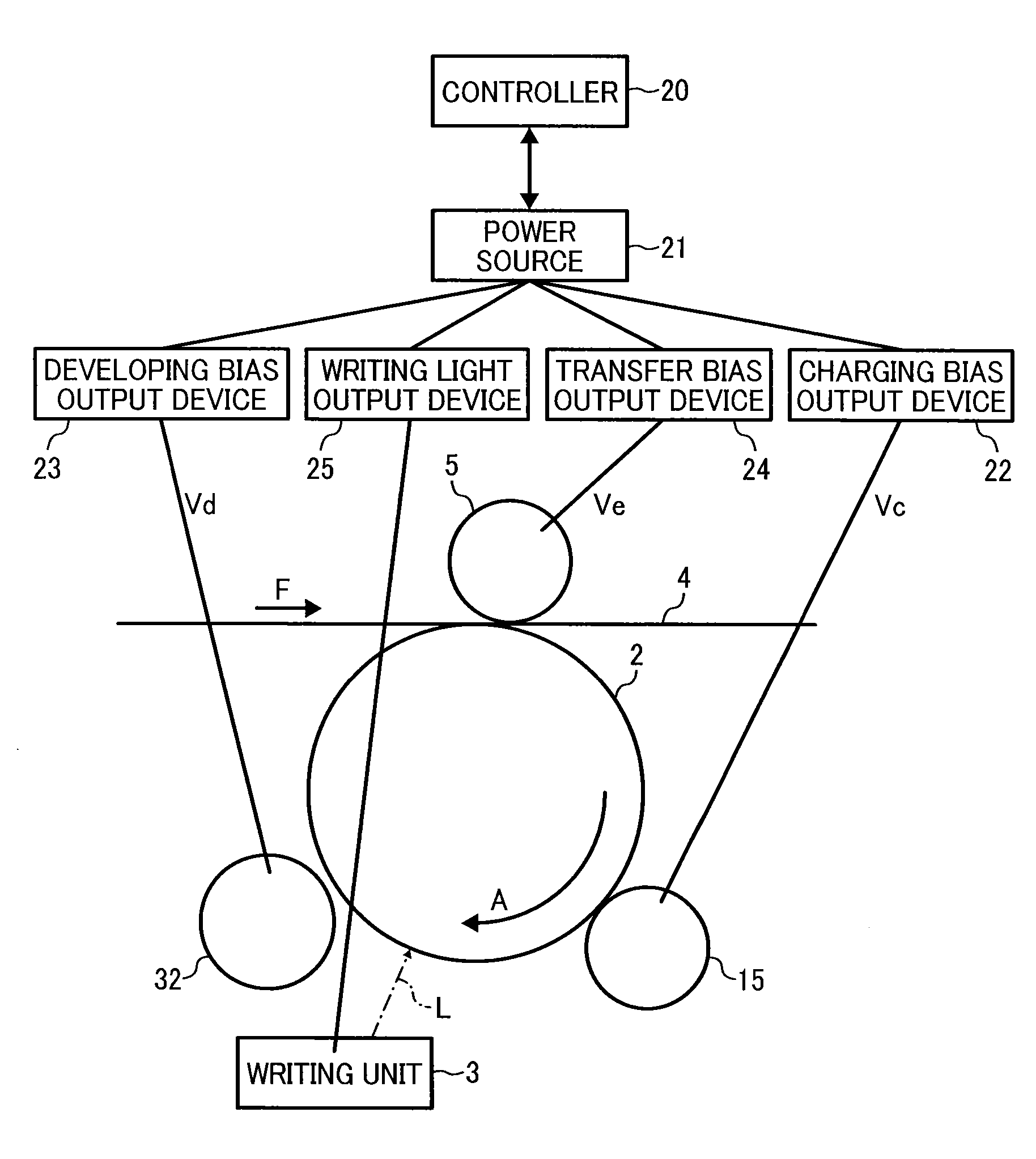
An image forming apparatus includes a charging bias output device, a developing bias output device, a transfer bias output device, and a controller. The controller controls the transfer bias output device to supply a transfer bias from a time at which a first position of a photosensitive member arrives at a transfer position after the charging bias output device starts supplying a charging bias. An initial value of the transfer bias is controlled to be smaller than a normal set value for a predetermined time period (Tc) which is a time after the transfer bias starts to be supplied and within a time corresponding to a rise time (Ta) during which a surface potential of the photosensitive member reaches a predetermined potential after the charging bias starts to be output. The first position of the photosensitive member is a position at which the charging device start charging the photosensitive member.

Description

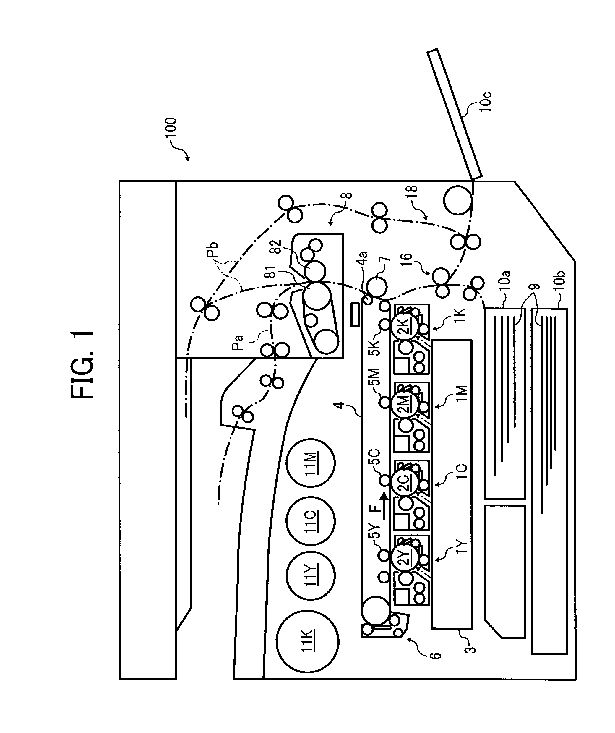
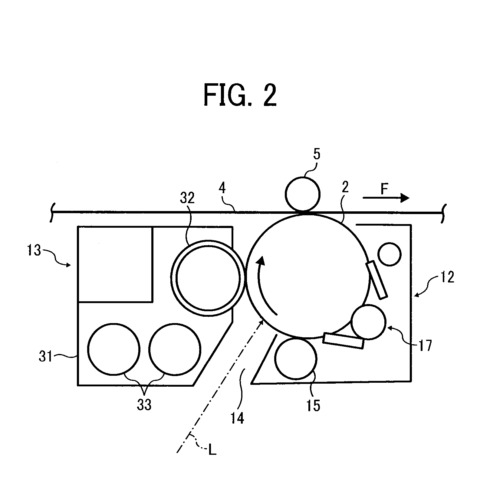
CROSS-REFERENCE TO RELATED APPLICATIONS[0001]This patent application is based on and claims priority pursuant to 35 U.S.C. §119 to Japanese Patent Application No. 2013-042633, filed on Mar. 5, 2013, in the Japan Patent Office, the entire disclosure of which is hereby incorporated by reference herein.BACKGROUND[0002]1. Technical Field[0003]Exemplary aspects of the present disclosure generally relate to an electrophotographic image forming apparatus, more particularly to a transfer bias control employed in an image forming apparatus.[0004]2. Description of the Related Art[0005]Image forming apparatuses such as a copier, a printer, a facsimile machine, and a digital multi-functional system including a combination thereof generally employ an electrophotographic method.[0006]The image forming apparatuses of this kind form an electrostatic latent image by charging uniformly a surface of a photosensitive member and illuminating the charged surface with laser light associated with an image ...

Claims


Application Information

Patent Timeline
Patent Type & Authority Applications(United States)
IPC IPC(8): G03G15/00G03G15/16G03G15/02
CPCG03G15/1675G03G15/065G03G15/0266
Inventor YOSHIDA, RYUJIZEMBA, HIDEKIMITANI, YUSUKEHOSHI, SHOTAROSHAKUTO, MASAHIKOMAEDA, HIROAKI
Owner RICOH KK
Learn More