Portable projection and display system

a projection system and display system technology, applied in the field of projection and display systems, can solve the problems of not being as sturdy or stable as is desirable, difficult to adjust, and difficult to set up, so as to shorten or lengthen the overall length, shorten or lengthen the distance, and facilitate manipulation

Active Publication Date: 2014-09-11
HDT EXPEDITIONARY SYST
View PDF21 Cites 15 Cited by
  • Summary
  • Abstract
  • Description
  • Claims
  • Application Information

AI Technical Summary

Benefits of technology

[0006]A counterweight bar, counterbalancing bar, or other counterweight or counterbalancing mechanism can be attached to the display system to offset the weight of a projector attached to the boom. The counterweight bar, for example, can attach to a rear bottom portion of the display system, such as to a rearward, bottom portion of the vertical support members. Support legs can also be attached to the bottom portion of the vertical support members and extend a desired distance in a forward direction from the support members to provide stability to the display system.
[0007]A projector can be attached to the display system via an adjustable boom. One end of the adjustable boom preferably includes a mechanism that attaches a projector to the boom. In one embodiment, this can be a ball mount for instance. A bracket having a ball mount can be securely connected to the projector. A ball receptacle can be arranged at the projector connection end of the adjustable boom. The ball mount can be arranged in the ball receptacle and a thumb screw can be tightened to secure the ball in the ball mount with the projector arranged in its desired orientation. The orientation of the projector with respect to the display system can then be easily manipulated by loosening the screw until the ball can be rotated within the ball mount. Once the desired orientation is achieved, the screw can be tightened to secure the projector in place. The vertical height of the projector and its distance from the display screen can preferably be manipulated using the adjustable boom assembly.
[0008]In one embodiment, the adjustable boom is hingedly attached to a boom bracket arranged along the top support member. The boom bracket provides a fulcrum for raising or lowering the projector. A boom adjuster, such as a boom adjustment bar can be used to connect a rearward end (opposite the projector connection end) of the boom to the middle support member (or other desired frame location). A removable hitch pin, for instance, can be arranged through mating holes to connect the bottom end of the boom adjustment bar to the middle support member. The boom adjustment bar can be hingedly connected to the rearward end of the boom to permit adjustment of an angle formed between the boom and the boom adjustment bar when adjusting a vertical position of a projector connection end of the boom. The boom adjuster preferably allows the project

Problems solved by technology

Other projection systems, such as those disclosed in U.S. Pat. Nos. 7,290,888 and 6,736,516, for example, may be more compl

Method used


Image

  • Portable projection and display system
  • Portable projection and display system
  • Portable projection and display system

Examples


Embodiment Construction

[0027]Various features, benefits, and configurations incorporating principles described herein for illustrative embodiments are shown in the accompanying drawings. Additional features, benefits and configurations will be readily apparent to those of ordinary skill in the art based on this disclosure and all such features, benefits and configurations are considered to be within the scope of the present invention.

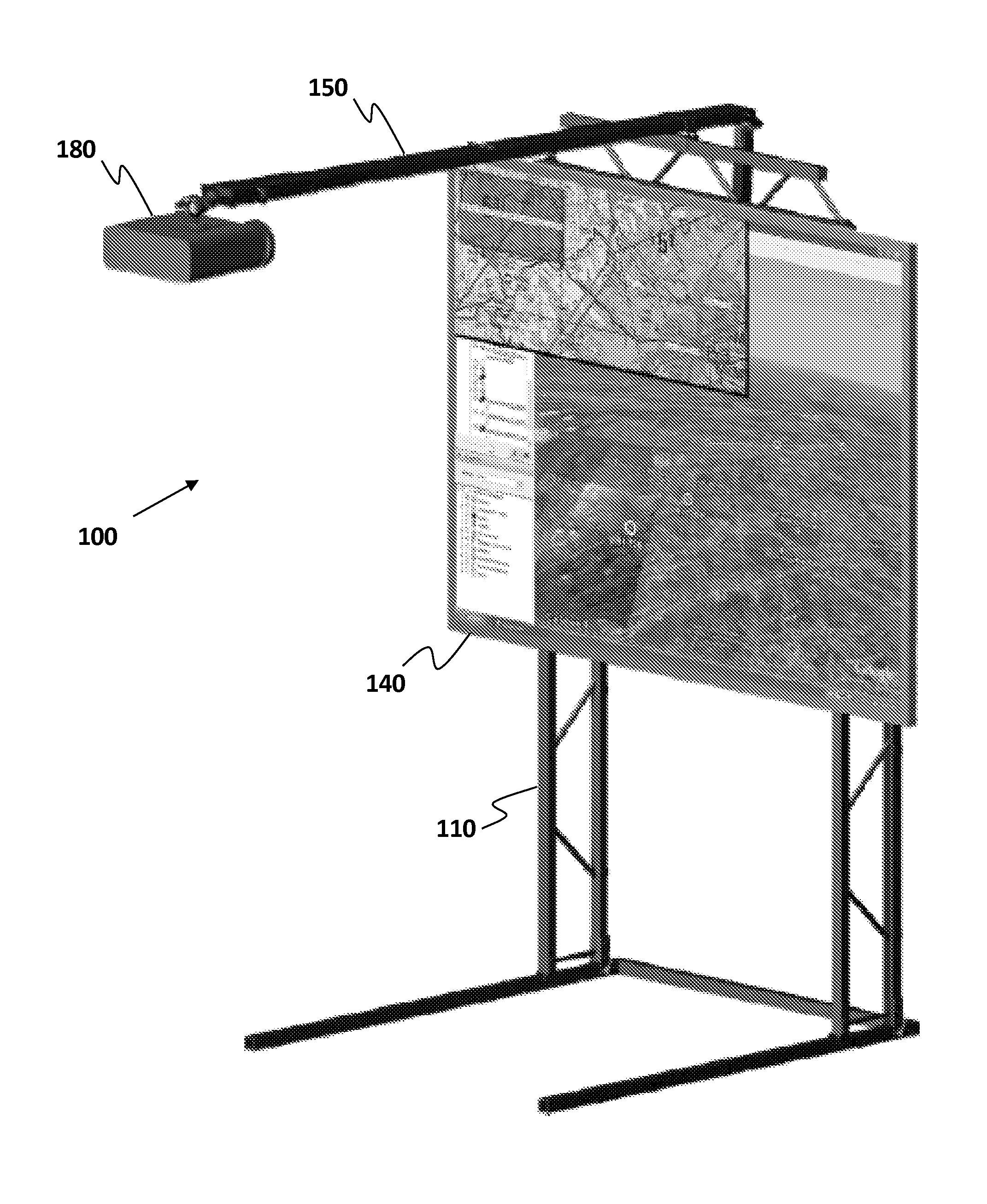
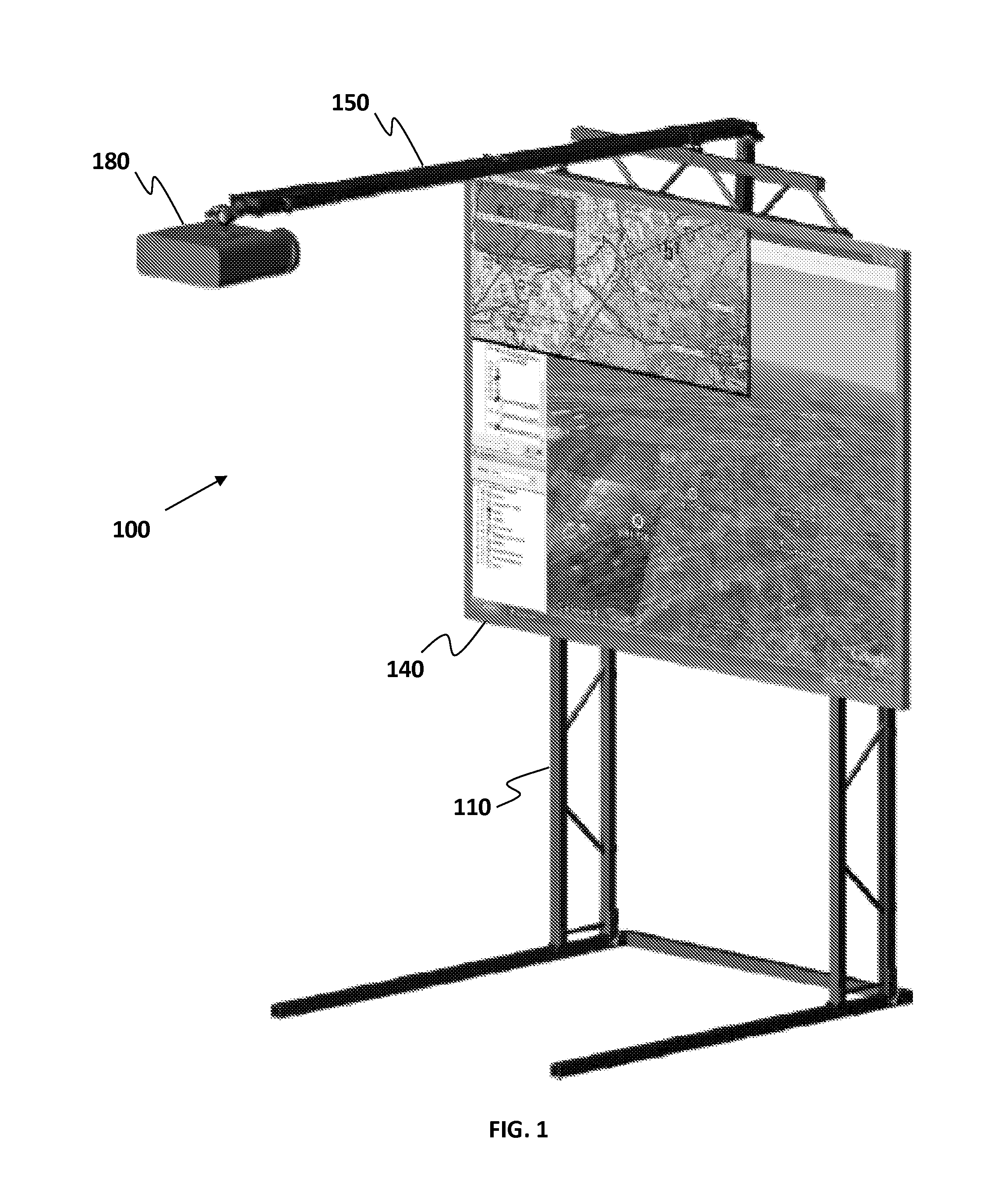
[0028]Various illustrative embodiments will now be described in connection with the accompanying drawings. FIG. 1 is a somewhat schematic perspective view of a portable projection and display system 100 according to one example embodiment. Referring to FIG. 1, the portable projection and display system 100 can include a display frame 110 having a display screen 140 mounted thereon. A projector 180 can be attached to the display system 100 via an adjustable boom 150. The portable projection and display system 100 is preferably configured to permit easy setup and takedown of th...


PUM

PropertyMeasurementUnit
Lengthaaaaaaaaaa
Structureaaaaaaaaaa
Sizeaaaaaaaaaa

Abstract

A portable projection and display system can include a frame assembly comprising one or more folding trusses, a counterweight bar arranged on a rearward bottom portion of the frame to help provide a stable base, and an adjustable boom. A projector can be mounted on one end of an adjustable boom. The boom can be configured to be capable of adjusting a distance between the projector and the display screen. The boom can be mounted to the frame with a hinged connection to permit it to act as a lever to raise and lower the projector. An adjustable boom bar can further be provided. The adjustable boom bar can be attached to an end of the boom opposite the projector such that adjustment of the boom bar raises and lowers the projector via a lever action about a fulcrum.

Description

TECHNICAL FIELD[0001]This disclosure relates generally to projection and display systems. More particularly, this disclosure relates to a portable projection and display system that permits easy setup and take down of the display stand and further facilitates easy adjustment of the projection and display components.SUMMARY OF THE DISCLOSURE[0002]According to various embodiments and principles disclosed herein, a portable projection and display system can provide numerous improvements over the prior art. Other projection systems, such as those disclosed in U.S. Pat. Nos. 7,290,888 and 6,736,516, for example, may be more complex to set up, take down, store, and transport, may be harder to adjust, and may not be as sturdy or stable as is desirable.[0003]According to one aspect of the present disclosure, a portable projection and display system can include support members comprising trusses. Left, right, middle and upper trusses can be used, for example, to provide strong support and st...

Claims


Application Information

Patent Timeline
IPC IPC(8): G03B21/30
CPCG03B21/30G03B21/10G03B21/58Y10T29/49826Y10T29/49842F16M11/00F16M11/04F16M11/22F16M13/022F16M2200/08G03B21/145
Inventor COREY, ROBERT W.ANDERSON, WILLIAM H.INDELICATO, PAUL JOSEPH
Owner HDT EXPEDITIONARY SYST
Why Eureka
Try Eureka