
Single motor dynamic calibration unit

a single motor and dynamic calibration technology, applied in the field of testing can solve the problem of time-consuming process of calibration of triaxis mems sensors

Active Publication Date: 2014-09-04
KIONIX CORP
View PDF5 Cites 4 Cited by
  • Summary
  • Abstract
  • Description
  • Claims
  • Application Information

AI Technical Summary

Benefits of technology

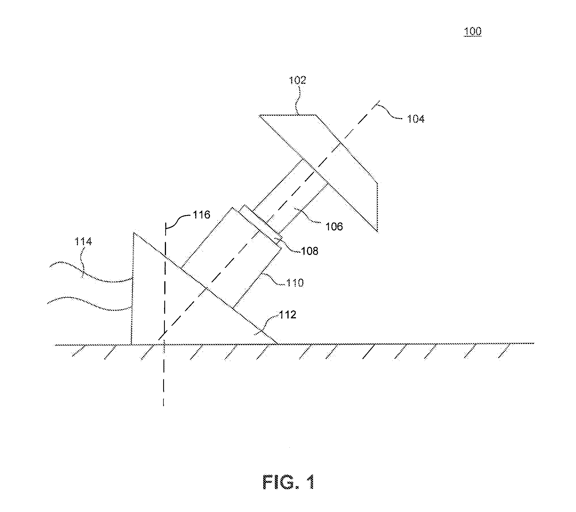
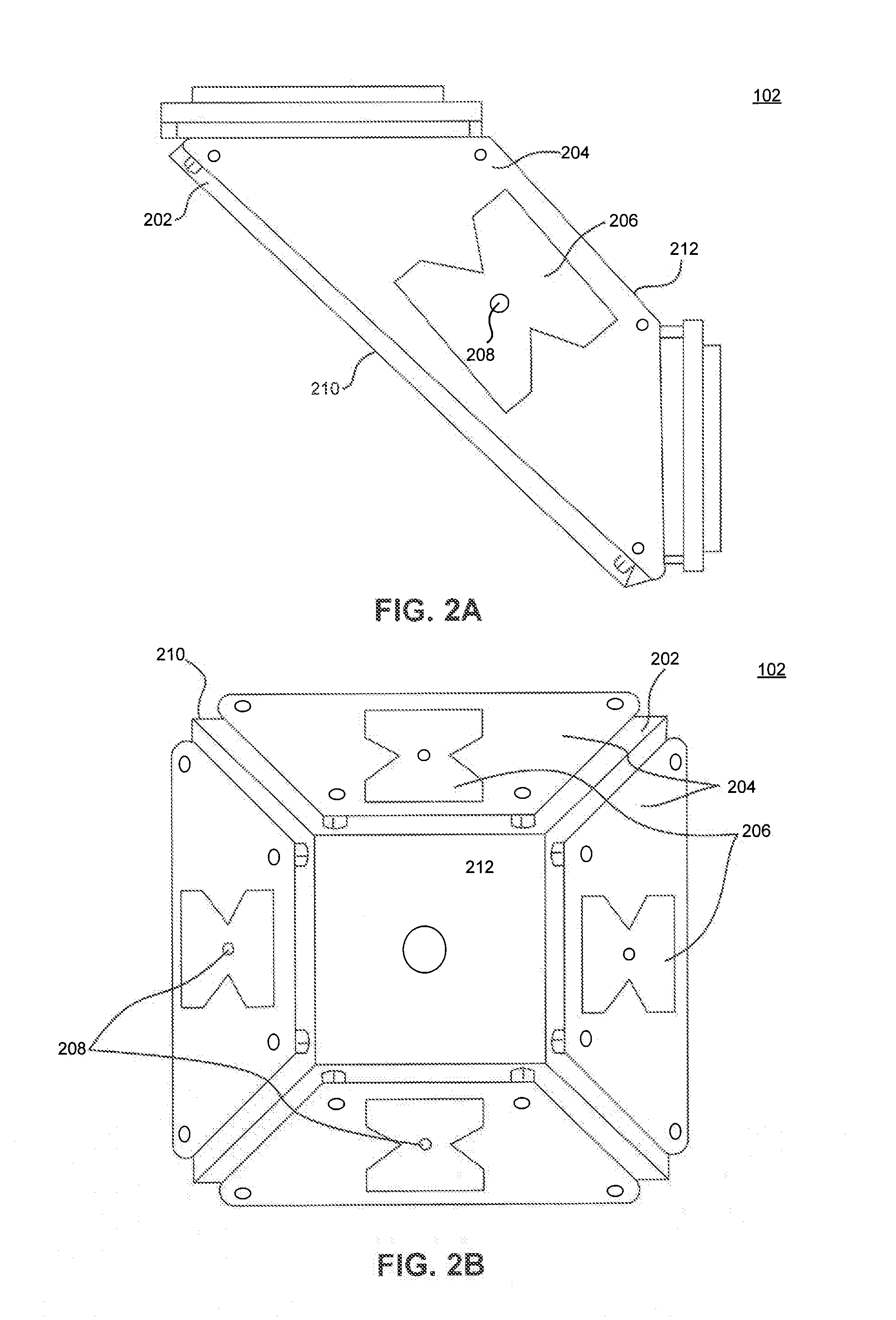
The patent is about a calibration unit, system, and method that use a single axis rotational unit to calibrate devices under test on a position using excitation along at least three degrees of freedom. The calibration unit includes a test head designed in the shape of a four-sided frustum. The calibration method uses gravitational excitation, Helmholtz coil excitation, rotational rate excitation, and rotational acceleration excitation for calibrating the device under test. This calibration system and method provide a way to accurately calibrate devices such as triaxis MEMS devices.

Problems solved by technology

But calibrating triaxis MEMS sensors is a time-consuming process.

Method used


Image

  • Single motor dynamic calibration unit
  • Single motor dynamic calibration unit
  • Single motor dynamic calibration unit

Examples


example method

for Calibrating a Triaxis MEMS Sensor

[0050]FIG. 3 is a flowchart of a method 300 for calibrating a triaxis MEMS sensor, according to an embodiment.

[0051]At step 302, a device under test (DUT) is loaded onto a test head. In an embodiment, the device under test is a triaxis MEMS sensor, The DUT is loaded onto the test head at a loading position, for example the top position for testing surface 200 described above. In an embodiment, more than one DUT can be loaded onto the test head.

[0052]At step 304, the test head is rotated around a single rotation axis, for example spin axis 104 described above. The DUT is rotated to a first fixed testing position. In an embodiment, the calibration unit has four testing heads and the DUT is rotated 90 degrees around the single rotation axis. In an embodiment, calibration testing can be performed while the DUT is being rotated. This testing during rotation is considered dynamic testing. In an embodiment, the speed of the rotation can be controlled to...


PUM


Abstract

A calibration unit, system, and method for calibrating a device under test are provided. The calibration unit, system, and method use a single axis rotational unit to calibrate devices under test on a test head. The single axis rotation unit is configured to extend at an angle from a known axis. The test head can be designed in the shape of a frustum with multiple sides. The calibration unit, system, and method can use combinations of gravitational excitation, Helmholtz coil excitation, and rotational rate excitation for calibrating the device under test. The calibration unit, system, and method can calibrate a 3 degree for freedom or higher MEMS devices.

Description

BACKGROUND[0001]1. Field[0002]The embodiments are directed generally to calibrating devices under test, and specifically, to calibrating triaxis MEMS sensors by rotating the devices around a single axis.[0003]2. Background Art[0004]A triaxis MEMS sensor is a device that can sense its orientation relative to a given axis, for example the axis defined by earth's local gravitational field. More generally, a triaxis MEMS sensor can measure excitation in at least three orthogonal directions.[0005]Within a triaxis MEMS sensor, there can be multiple sense elements capable of sensing different physical inputs. These sensors that are capable of sensing multiple physical inputs are sometimes referred to as combination sensors. For example, a triaxis MEMS sensor could simply comprise a triaxis accelerometer and, therefore, be considered a three degree-of-freedom (DOF) system—one DOF for each dimension in physical space. If a triaxis gyroscope were combined with the triaxis acceleration sensor,...

Claims


Application Information

Patent Timeline
IPC IPC(8): G01D18/00G01B21/00
CPCG01B21/00G01D18/00B81C99/005
Inventor STIRLING, NATHAN L.DEWALT, LUKE E.STRAIT, JAMES E.ADAMS, SCOTT G.
Owner KIONIX CORP
Learn More