
Pluggable self locking connector

a self-locking, connector technology, applied in the direction of coupling device connection, medical science, surgery, etc., can solve the problems of paramedic loss, paramedics may feel physically and mentally unsecure, and front line paramedics are still at risk of bacterial or viral infection due to unsuitable protection,

Inactive Publication Date: 2014-08-21
NEXTRONICS ENG CORP
View PDF7 Cites 23 Cited by
  • Summary
  • Abstract
  • Description
  • Claims
  • Application Information

AI Technical Summary

Benefits of technology

The patent describes a connector that prevents a plug from coming back into the socket. This is accomplished by designing the plug shell and the snap fit portion of the connector. The socket case has a depression and the snap fit portion has a resilient rib that fit tightly into the depression, ensuring a secure connection and avoiding signal interruption. The connector is also designed to prevent the plug from coming back into the socket by using a resilient positioning member that interacts with the socket case.

Problems solved by technology

In the case of highly infectious diseases (e.g., severe acute respiratory syndrome, smallpox, tuberculosis and the like), although relevant regulation has been applied, the front line paramedics are still at risk to bacterial or viral infection because of unsuitable protection.
This may further lead to the loss of paramedics.
Paramedics may feel physically and mentally unsecure when conducting the treatment.
The tubular locking connector cannot be fastly detached in emergency.
Also, the tubular locking connector may easily fall off upon impact, and the signal transmission is interrupted.
The conventional connector cannot satisfy the high standard in the case of highly infectious diseases; especially in the operation room, surgery and the like.
Thus, large amount of time and labor is investigated in sterilizing the medical device to avoid secondary infection.
The cost of human and medical source is considerable.

Method used


Image

  • Pluggable self locking connector
  • Pluggable self locking connector
  • Pluggable self locking connector

Examples


Embodiment Construction

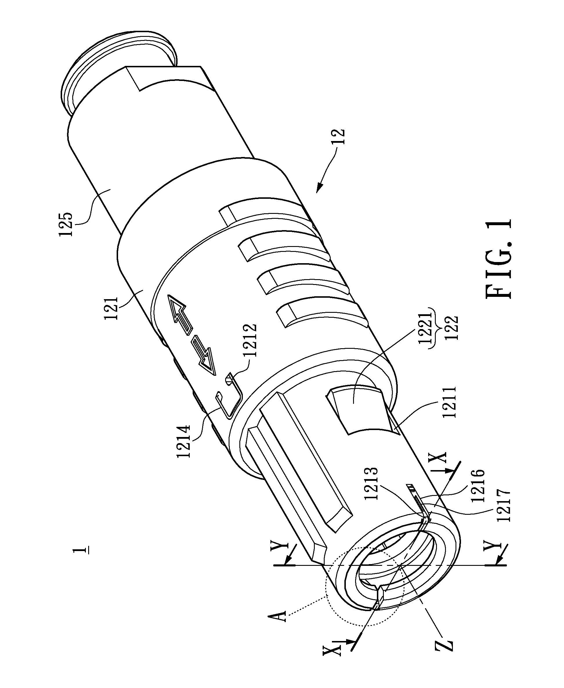
[0027]The aforementioned illustrations and following detailed descriptions are exemplary for the purpose of further explaining the scope of the instant disclosure. Other objectives and advantages related to the instant disclosure will be illustrated in the subsequent descriptions and appended drawings. The instant disclosure provides a pluggable self locking connector 1, which satisfies water proof IP50. The connector 1 is a disposable tubular multi-core connector for surgical use. The connector 1 may also be a tubular multi-core connector which satisfies water proof IP50 and IP68 for precision medical instrument and the instant disclosure is not limited thereto. In other words, the pluggable self locking connector 1 can be implemented to other machines.

[0028]Please refer to FIGS. 1 to 8B. As shown in FIGS. 1, 2 and 4A, the pluggable self locking connector 1 includes a socket 11 (shown in FIG. 4A) and a plug 12. The socket 11 can mate with the plug 12 (as shown in FIG. 6A), and the ...


PUM


Abstract

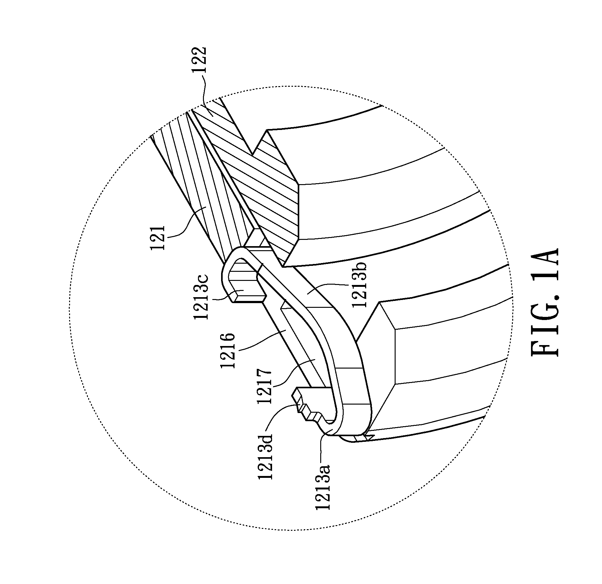
A pluggable self locking connector includes a socket having a socket case and a plug having a plug shell and a snap fit portion coupled thereto. The socket case is formed with a depression on the inner wall. The outer wall of the snap fit portion is formed with a deformable resilient rib and a bump. The plug shell is formed with an opening for receiving the resilient rib and a resilient latch corresponding to the bump. The front end of the plug shell has a resilient positioning member. When the socket and plug mate, the resilient rib slides into the depression. When the socket and the plug separate, the resilient rib is confined within the depression and the resilient latch and the bump are engaged. The front end of the snap fit portion presses the resilient positioning member and the resilient positioning member is partially exposed.

Description

BACKGROUND[0001]1. Field of the Invention[0002]The instant disclosure relates to a connector; in particular, to a self locking connector for preventing repeated plugging / drawing, applicable to disposable medical device.[0003]2. Description of Related Art[0004]In the case of highly infectious diseases (e.g., severe acute respiratory syndrome, smallpox, tuberculosis and the like), although relevant regulation has been applied, the front line paramedics are still at risk to bacterial or viral infection because of unsuitable protection. This may further lead to the loss of paramedics. Paramedics may feel physically and mentally unsecure when conducting the treatment. If a paramedic is infected and continues his or her routine, the disease may spread among any people within close contact.[0005]However, the conventional connector used in medical device (e.g., monitoring device, imaging device and the like) can be a tubular locking connector or a tubular re-pluggable connector. The tubular...

Claims


Application Information

Patent Timeline
Patent Type & Authority Applications(United States)
IPC IPC(8): H01R13/627
CPCH01R13/6277H01R13/6273H01R13/633A61B2018/00178A61B2017/0023H01R13/506
Inventor SU, HOU-ANYANG, HAI-WENXIAO, XIN-CHAO
Owner NEXTRONICS ENG CORP
Learn More