
Dual-stage parabolic concentrator

a parabolic concentrator and concentrator technology, applied in the direction of solar-ray concentration, photovoltaics, solar heat collectors with working fluids, etc., can solve the problems of losing a considerable portion of the energy directed towards the existing absorber/receiver design, and achieve the effect of improving the efficiency of the concentrator and the absorber/receiver subsystem, improving the efficiency of the csp, and improving the efficiency of the on

Active Publication Date: 2017-12-12
LAKSHMANAN KARTHIGUEYANE +1
View PDF7 Cites 0 Cited by
  • Summary
  • Abstract
  • Description
  • Claims
  • Application Information

AI Technical Summary

Benefits of technology

[0011]When it comes to improving efficiency of a CSP, CPV or CHTPV system, it can be done by improving the efficiency of one or more of the various subsystems involved such as concentrator, absorber / receiver, Sun tracking mechanism, heat transfer fluid, thermal energy storage, heat engine / steam turbine, electricity generator, photovoltaic cells, etc. The present invention attempts to improve the efficiency of the concentrator and absorber / receiver subsystem.
[0012]A basic convention being followed in designing solar concentrators with multistage reflectors is to avoid reentry of a ray in any of the stages. However, the concentrator design proposed in this invention violates this convention in an effort to achieve a higher conversion efficiency. Another key area to be improved in existing CSP systems is the efficiency of absorbers / receivers. Since the absorptivity of the absorber's surface cannot be 100% and as the speed of light is much higher than the rate at which heat is transferred through the absorber's / receiver's surface, existing absorber / receiver designs loses a considerable portion of the energy directed towards it. The same case applies for PV based systems too. To overcome this, the present invention allows for a slow, gradual and complete absorption of heat and / or light energy from the concentrated beam of sunlight.
[0015]For CHTPV systems, apart from direct conversion of light energy to electrical energy using photovoltaic panels, heat energy generated by them would be absorbed in a way similar to CSP systems. This improves the overall system efficiency.

Problems solved by technology

Since the absorptivity of the absorber's surface cannot be 100% and as the speed of light is much higher than the rate at which heat is transferred through the absorber's / receiver's surface, existing absorber / receiver designs loses a considerable portion of the energy directed towards it.

Method used


Image

  • Dual-stage parabolic concentrator
  • Dual-stage parabolic concentrator
  • Dual-stage parabolic concentrator

Examples


Embodiment Construction

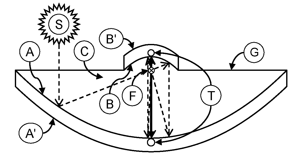
[0022]Referring to FIG. 1, a simplest schematic diagram of Dual-Stage Parabolic Concentrator is illustrated, to describe the principle behind this design.

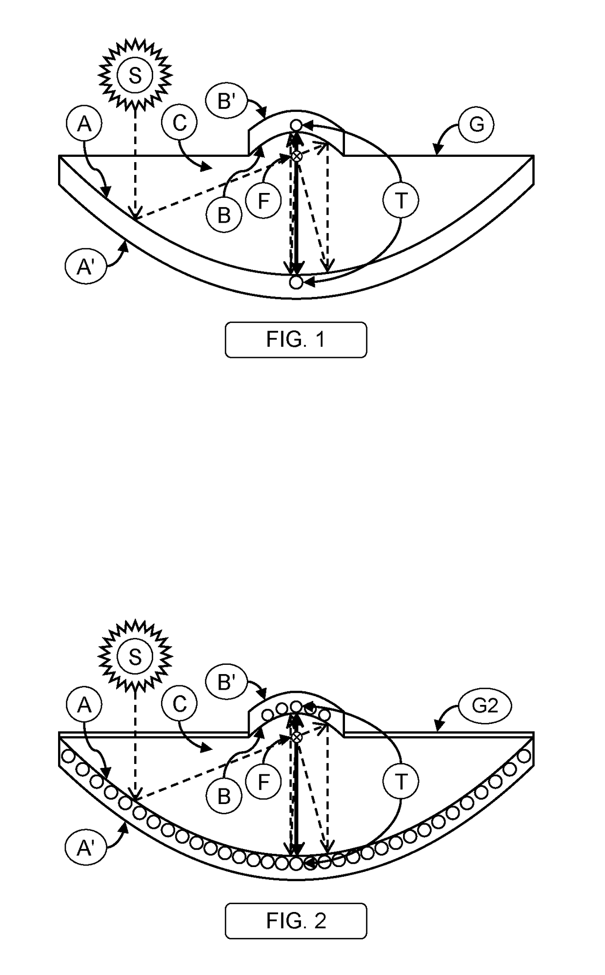
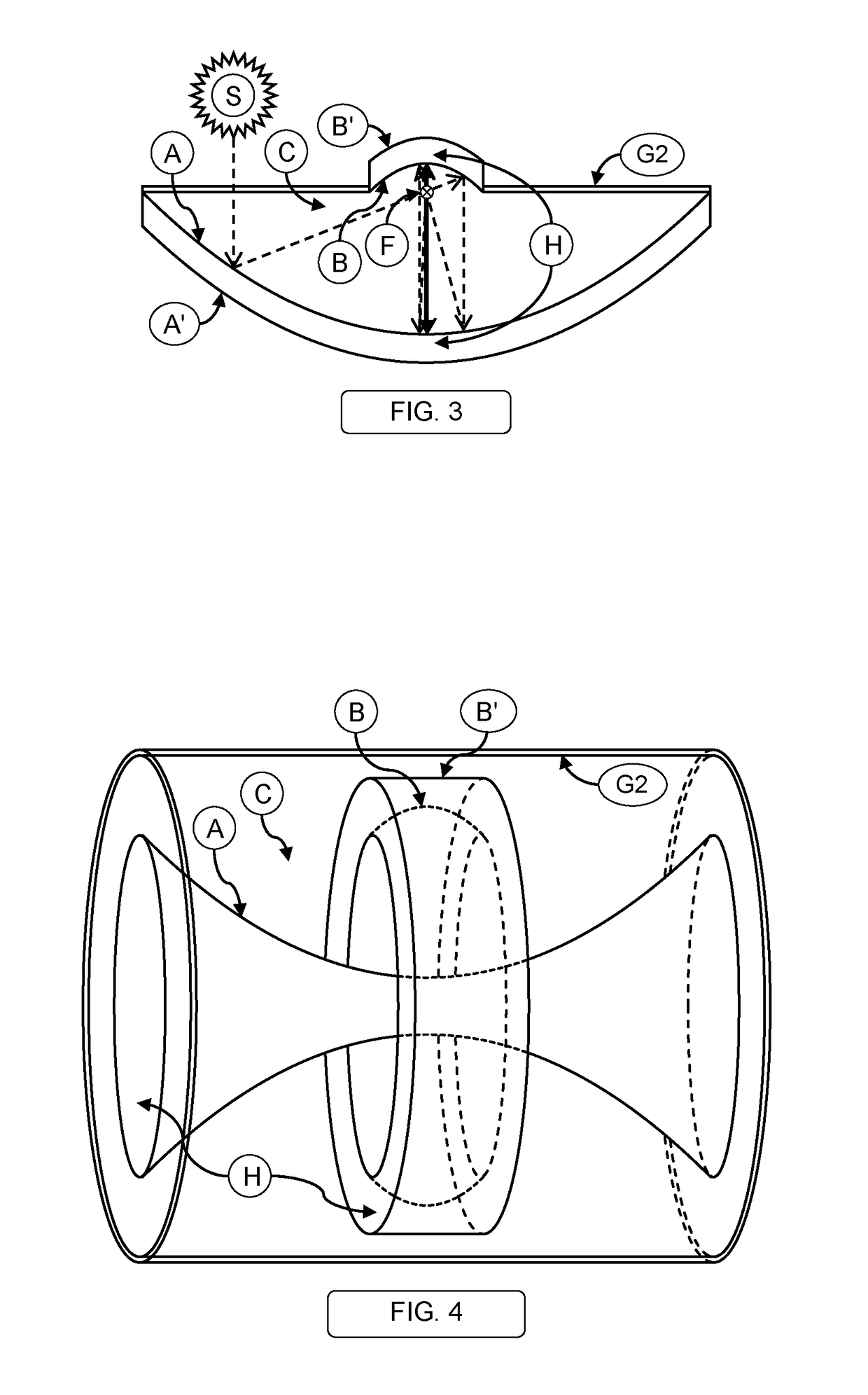
[0023]The Dual-Stage Parabolic Concentrator proposed in this invention comprises of a larger primary parabolic reflector (A) whose aperture would always face the Sun (S) directly with the help of a Sun tracking mechanism (not shown in figure) and a smaller secondary parabolic reflector (B) whose aperture would face the primary reflector's aperture. These two reflectors would be arranged in a way such that their focal point / line (F) and axes coincides with each other. A plurality of Absorber Tubes (T) for carrying heat transfer fluid would be placed at the vertex (as shown in FIG. 1) and / or throughout the surface of both the reflectors on their external (non-reflecting) side (as shown in FIG. 2). These tubes, along with the non-reflecting surface of the reflectors would be covered / sealed with appropriate thermal insulation (not show...


PUM


Abstract

An improvised Solar Concentrator and Absorber / Receiver Subsystem using a Dual-Stage Parabolic Concentrator for Concentrating Solar Power (CSP) (Thermal) system comprises of two parabolic mirrored reflectors wherein their apertures face each other with their focal point / line and axes coincides with each other, a plurality of absorber tubes / cavities placed on the non-reflecting side of the primary and / or secondary reflectors to carry heat transfer fluid, combined with relevant mechanisms to prevent / minimize thermal loss, mounted on a Sun tracking mechanism. For Concentrating Photovoltaic (CPV) and Concentrating Hybrid Thermo-Photovoltaic (CHTPV) Systems, all or a portion of the reflectors' reflecting and / or exterior surfaces would be covered or substituted with suitable photovoltaic panels.

Description

FIELD OF THE INVENTION[0001]The present invention relates to the field of power generation systems. The present invention specifically relates to a system to convert energy from solar radiation into a concentrated beam of light which in turn is converted into other forms of usable energy such as heat, mechanical work and / or electricity. In particular, this invention portrays a way to enhance efficiency of Concentrating Solar Power (Thermal and Photovoltaic) systems by using Dual-Stage Parabolic Concentrators in a specific configuration or arrangement.BACKGROUND OF THE INVENTION[0002]Solar energy is one of the popular and well known renewable source to produce clean energy. At present there are various means and methods to convert energy from solar radiation into other usable forms of energy such as heat, mechanical work and / or electricity. Majority of such systems are basically designed using Photovoltaic (PV), Concentrating Solar Power (CSP) (Thermal), Concentrating Photovoltaic (C...

Claims


Application Information

Patent Timeline
Patent Type & Authority Patents(United States)
IPC IPC(8): H01L31/0232H02S40/22H02S40/44F24J2/18H01L31/054H02S20/32F24J2/05F24J2/10F24J2/14H02S10/30F24J2/50F24S10/40F24S23/00F24S23/70F24S23/71F24S23/74F24S23/79F24S50/20
CPCH02S40/22F24J2/055F24J2/10F24J2/14F24J2/18H01L31/0547H02S40/44H02S20/32Y02E10/60F24J2/50F24J2002/502H02S10/30Y02E10/52F24S10/45F24S23/70F24S23/74F24S23/79F24S80/50F24S80/56F24S2080/502Y02E10/44Y02E10/40
Inventor LAKSHMANAN, KARTHIGUEYANELAKSHMANAN, RAJAGANAPATHY
Owner LAKSHMANAN KARTHIGUEYANE
Learn More