
High reliability armored termination/epoxy gland

a fiber optic cable and high reliability technology, applied in the direction of optical elements, manufacturing tools, instruments, etc., can solve the problems of high reliability, redundant penetration, more difficult tasks,

Inactive Publication Date: 2014-08-21
AFL COMM LLC
View PDF24 Cites 17 Cited by
  • Summary
  • Abstract
  • Description
  • Claims
  • Application Information

AI Technical Summary

Benefits of technology

The patent text describes a small device that connects a fiber optic cable to a pressure or splice housing. The device includes an armored termination that locks in the armor wires, sealing paths to prevent water from getting in between the armor wires and cable tubes, and fiber feed-through tubes to prevent water from getting in the cable tubes. This device prevents water from getting into the fiber optic cable and ensures a reliable connection between the cable and the pressure housing.

Problems solved by technology

One of the key challenges in subsea system design is to provide a high-reliability, redundant penetration into 1-atmosphere pressure housings.
This task is more difficult in subsea optical systems where a fiber optic cable must be cut to allow for interconnection within a pressure housing.
While wedge cones have sufficiently high strength, wedge cones and housings are specific to their cable type and are labor intensive to terminate.
Epoxy cones—cable tubes and armor wires glued in a cone—can be applied to many cable geometries, but the epoxy used degrades over time and effectiveness is dependent on manufacturing process repeatability.
Morrison seals provide bi-directional tube sealing while boot seals are limited to single direction sealing.
Because Morrison seals and boot seals only block leakage around a cable tube, they are ineffective in the event of a cable tube breach and leakage with in the cable tube.
The fibers and tubes are not individually isolated, however, and may allow pressurized water to leak from tube to tube.
Ferrule-based penetrators—where ferrule is soldered onto fiber—provides hermetic seal, but are expensive to deploy and requires additional splices in optical system.

Method used


Image

  • High reliability armored termination/epoxy gland
  • High reliability armored termination/epoxy gland
  • High reliability armored termination/epoxy gland

Examples


Embodiment Construction

[0017]Hereinafter, exemplary embodiments will be described in greater detail with reference to the accompanying drawings.

[0018]In the following description, same reference numerals are used for the same elements when they are depicted in different drawings. Elements are described in detail in order to assist in an understanding of exemplary embodiments. Thus, it is apparent that exemplary embodiments may be carried out without those specifically-defined elements. Detailed descriptions of known elements are omitted.

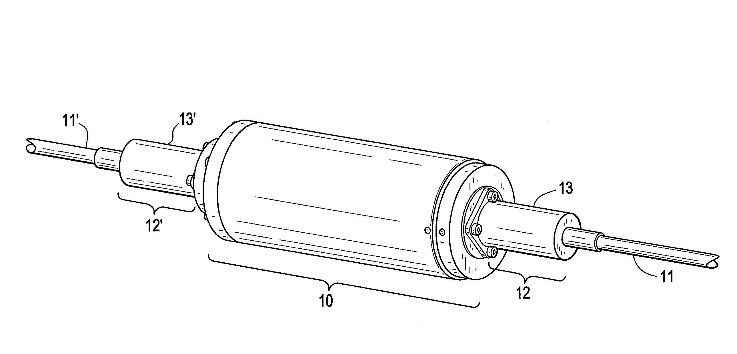
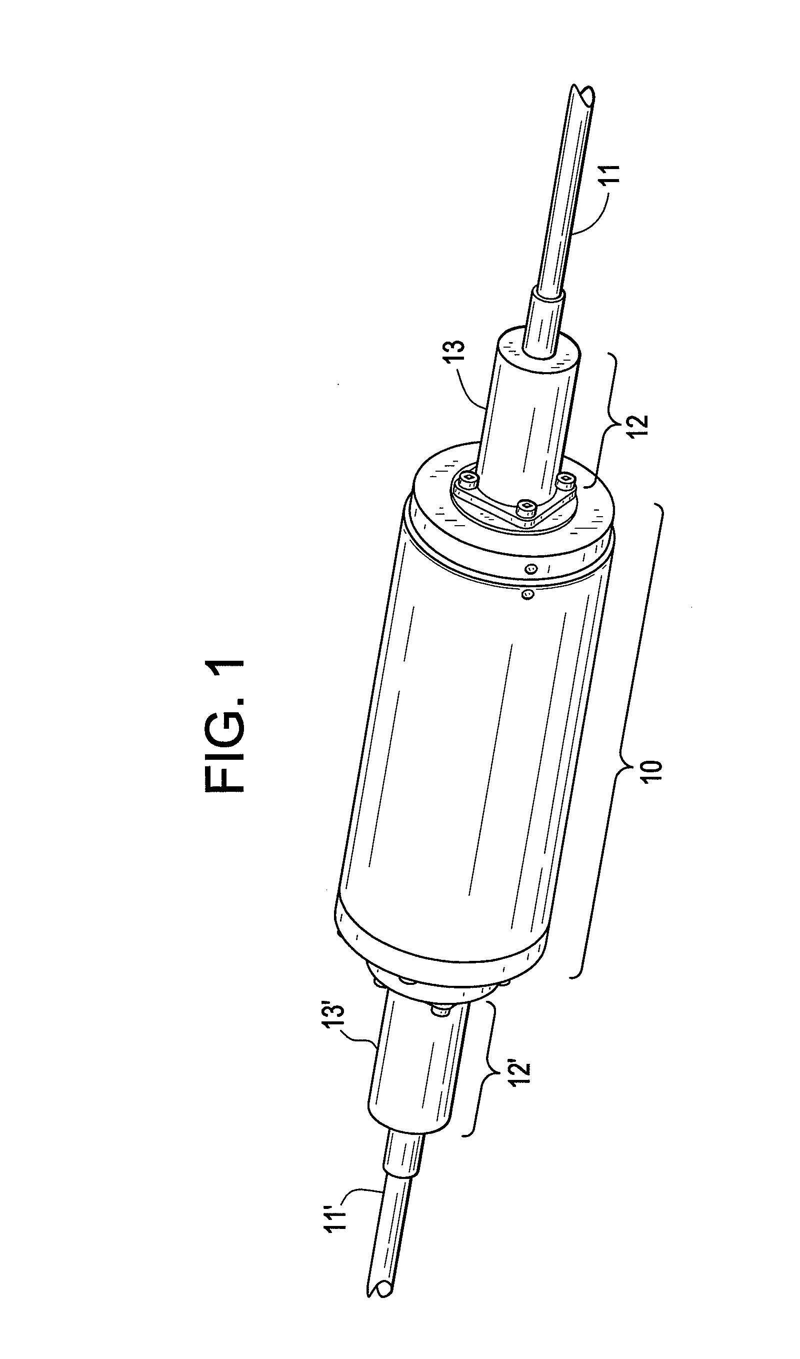
[0019]FIG. 1 illustrates a cable 11 connected to a pressure housing 10 according to exemplary embodiments.

[0020]Referring to FIG. 1, cable 11 is cut to form cable 11 and cable 11′ each of which join pressure housing 10 on opposite ends of pressure housing 10 to form an in-line connection. Cable 11 is joined to pressure housing 10 by armored cable termination / fiber-optic seal 12, the exterior portion of which may be covered by overmold 13. Similarly, cable 11′ is joined to ...


PUM

PropertyMeasurementUnit
pressureaaaaaaaaaa
break strengthaaaaaaaaaa
strain forcesaaaaaaaaaa

Abstract

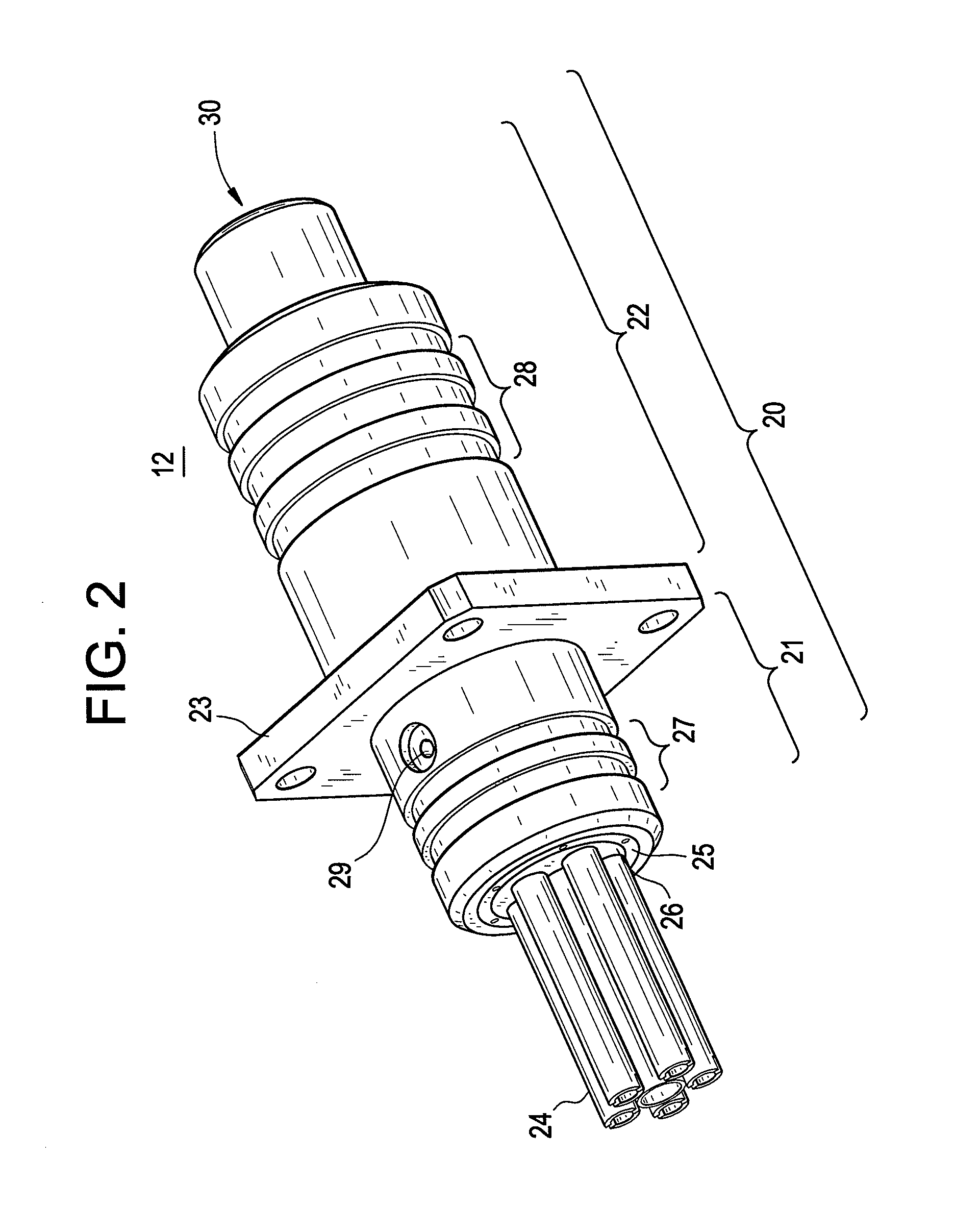
An armored cable termination / fiber-optic seal which connects a fiber optic cable—the fiber optic cable including one or more armor wires and one or more cable tubes—to a pressure housing, the armored cable termination / fiber-optic seal including: an armored termination which locks the one or more armor wires in a conical cavity; sealing paths which block water from traveling in the interstitial space between the one or more armor wires and the one or more cable tubes into the pressure housing; and fiber feed-through tubes which block water from traveling in the interior of the one or more cable tubes into the pressure housing.

Description

CROSS-REFERENCE TO RELATED APPLICATION[0001]This application claims the benefit of U.S. Provisional Patent Application No. 61 / 539,081, filed on Sep. 26, 2011, in the United States Patent and Trademark Office, the disclosure of which is incorporated herein by reference.BACKGROUND[0002]1. Field[0003]This application relates to termination of a subsea fiber optic cable, specifically a small form-factor armored cable termination / fiber-optic seal which facilitates a connection between a subsea fiber optic cable and a pressure housing in an environment with a pressure gradient between the external environment and the pressure housing interior.[0004]2. Description of Related Art[0005]One of the key challenges in subsea system design is to provide a high-reliability, redundant penetration into 1-atmosphere pressure housings. This task is more difficult in subsea optical systems where a fiber optic cable must be cut to allow for interconnection within a pressure housing. The termination goin...

Claims


Application Information

Patent Timeline
Patent Type & Authority Applications(United States)
IPC IPC(8): G02B6/44
CPCG02B6/4486G02B6/443G02B6/4428Y10T29/49826
Inventor KIMBRELL, EDDIETOTH, JOHNLICHOULAS, TEDGUZZO, LOU
Owner AFL COMM LLC
Learn More