Optical element, window material, fitting, and solar shading device
a technology for solar shading and optical elements, applied in the direction of optical elements, door/window protective devices, instruments, etc., can solve the problems of rising ambient temperature and the possibility of regularly reflecting incident solar light, and achieve the effect of suppressing color tone changes
Inactive Publication Date: 2014-08-21
DEXERIALS CORP
View PDF3 Cites 18 Cited by
- Summary
- Abstract
- Description
- Claims
- Application Information
AI Technical Summary
Benefits of technology
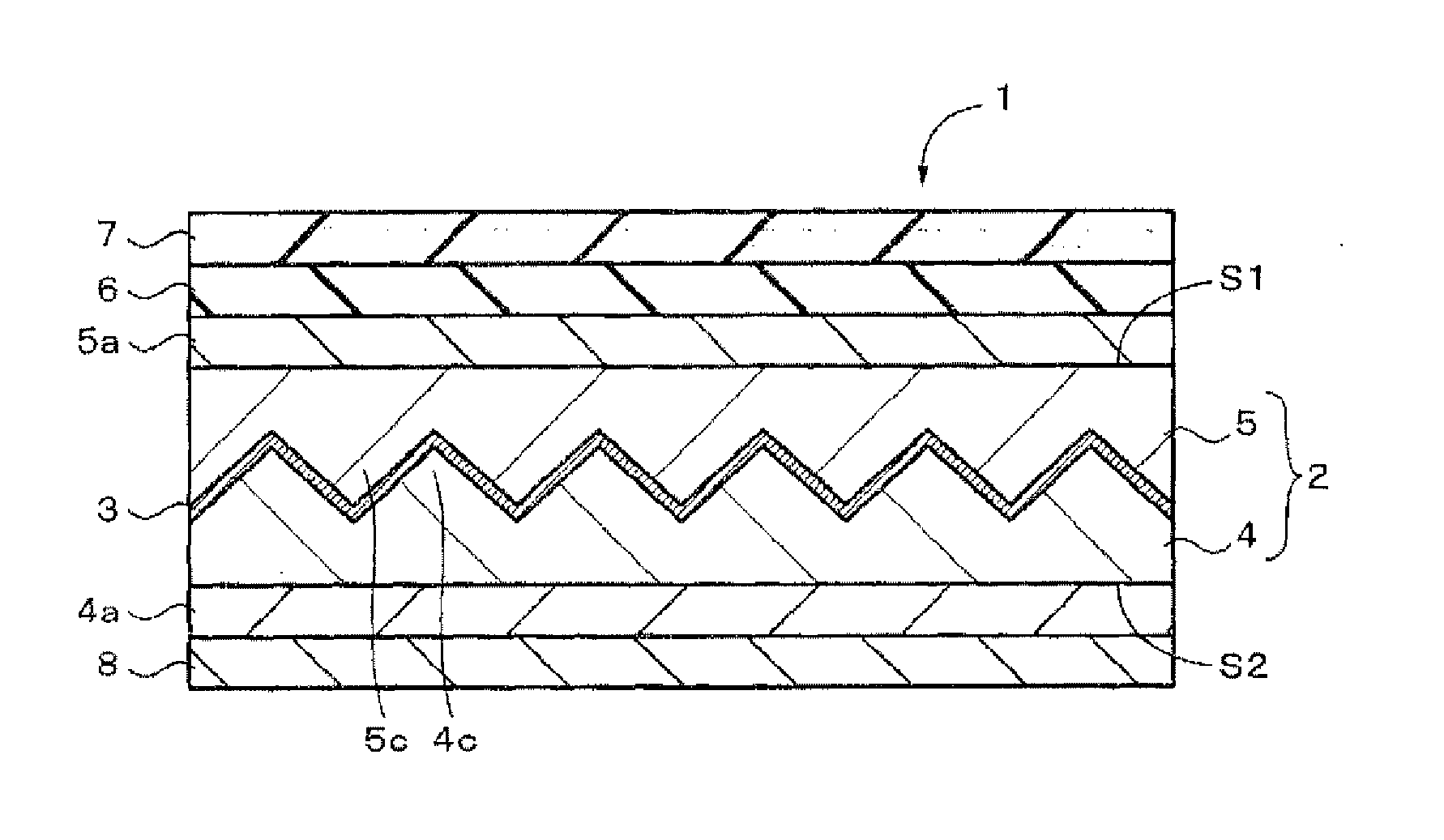
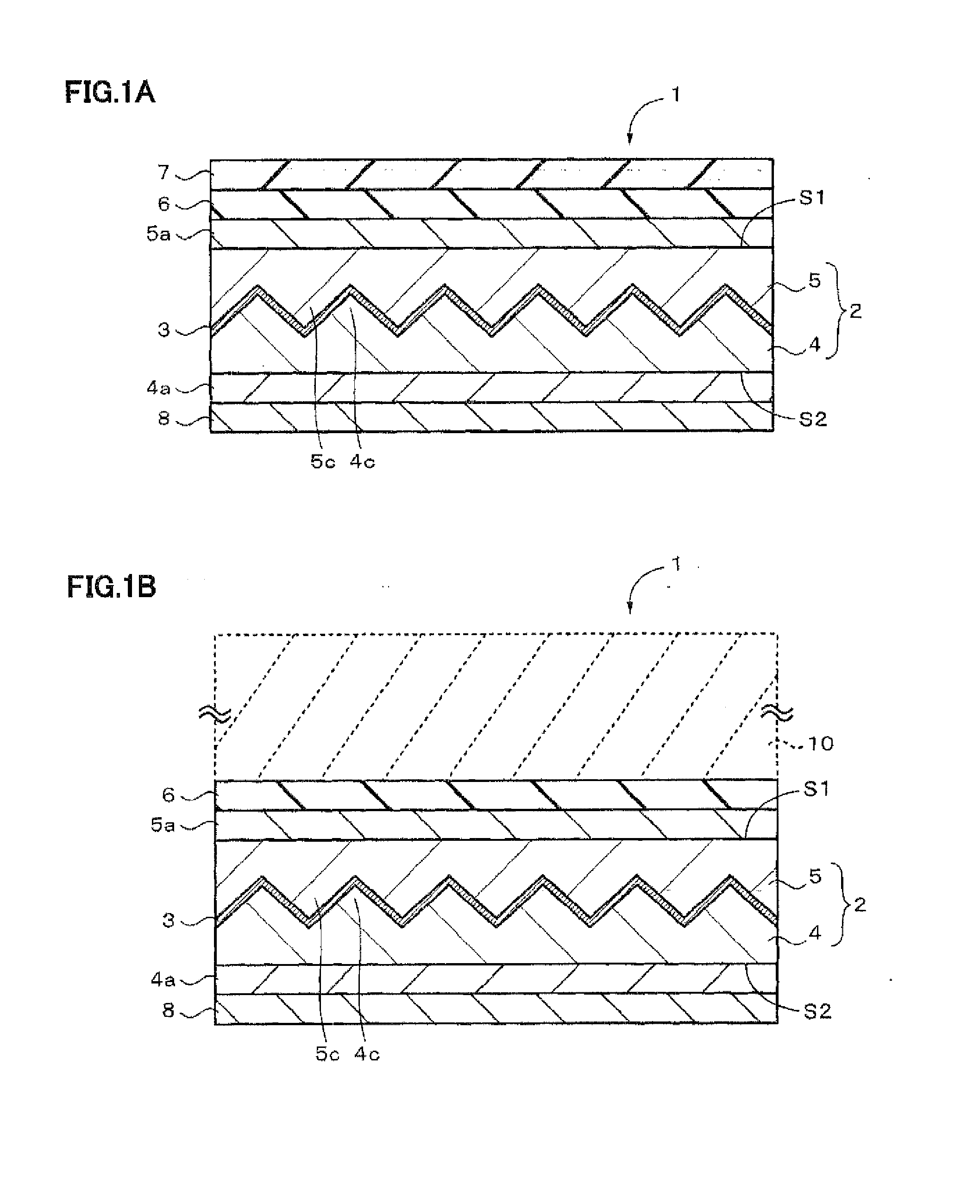
The present invention provides an optical element that can suppress a change in color tones caused by a change in incident angle. The optical element includes a first optical layer with a concave-convex surface, a wavelength-selective reflection layer formed on the concave-convex surface, and a second optical layer formed on the wavelength-selective reflection layer. The wavelength-selective reflection layer has a five-layer structure, with alternating high-refractive-index layers and metal layers. The ratio of the optical film thickness of the metal layer to the high-refractive-index layer is included in a first region surrounded by a formula, and the ratio of the optical film thickness of the third high-refractive-index layer to the first high-refractive-index layer is included in a second region surrounded by a formula. The optical element can be used in a window material, a fitting, a solar shading device, and other optical applications.
Problems solved by technology
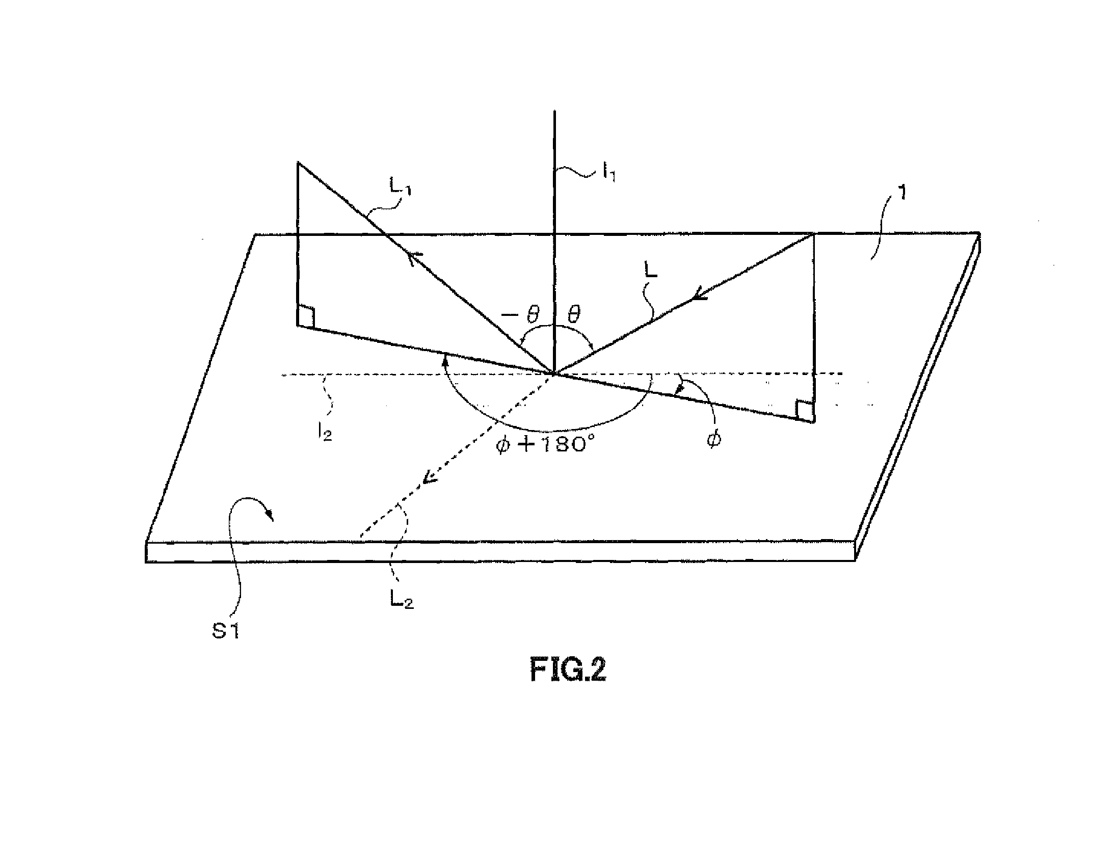
However, since such a reflection layer is formed on a flat-shaped film or a window glass, it is only possible to regularly reflect incident solar light.
For this reason, light rays applied from the sky and regularly reflected therefrom are allowed to reach another building outside and the ground, and absorbed and converted to heat, thereby causing a rise in the ambient temperature.
As a result, on the periphery of a building in which this reflection layer is bonded to the entire windows, a temperature rise is locally generated, with the result that such problems as to cause an increased heat island phenomenon in a city district and as to suppress lawn from growing only on an irradiated surface by the reflected light.
Method used
View moreImage
Smart ImageViewing Examples

Examples
first embodiment (
1. First Embodiment (example in which structural elements are one-dimensionally arranged)
second embodiment (
2. Second Embodiment (example in which a region is defined by an approximation straight line)
third embodiment (
3. Third Embodiment (example in which structural elements are two-dimensionally arranged)
Login to View More PUM
| Property | Measurement | Unit |
|---|---|---|
| thickness | aaaaa | aaaaa |
| thickness | aaaaa | aaaaa |
| thickness | aaaaa | aaaaa |
Abstract
An optical element is provided with a wavelength-selective reflection layer having a five-layer configuration in which high-refractive-index layers and metal layers are alternately stacked. The present invention is designed so that the ratio α of an optical film thickness db of the entire metal layer relative to an optical film thickness da of the high-refractive-index layers as a whole, and the ratio β (=d3 / d1) of an optical film thickness d3 of the third high-refractive-index layer with respect to the optical film thickness d1 of the first high-refractive-index layer as viewed from either the first optical layer side or the second optical layer side are included within a predetermined range.
Description
FIELD OF THE INVENTION[0001]This invention relates to an optical element that can suppress a change in color tone, a window material, a fitting and a solar shading device.BACKGROUND OF THE INVENTION[0002]In recent years, there have been increasing cases in which a layer for absorbing or reflecting one portion of solar light is attached to building-use glass and vehicle window glass of a high-rise building, a house or the like. This is one of energy-saving countermeasures to be carried out for preventing global warming, and its purpose is to reduce the load imposed on cooling facilities, caused by light energy that is applied from the sun and enters the inside of a housing through a window to cause a temperature rise of the inside of the housing. In the optical energy applied from the sun, a visible light region having wavelengths of 380 to 780 nm and a near infrared ray region having wavelengths of 780 to 2100 nm occupy a great ratio thereof. Of these, since the transmittance of the...
Claims
Login to View More Application Information
Patent Timeline
 Patent Type & Authority Applications(United States)
IPC IPC(8): G02B5/28C03C17/36G02B5/26
CPCG02B5/282C03C17/36E06B9/24G02B5/0231G02B5/0242G02B5/045G02B5/26G02B5/285C03C17/3657E06B2009/2417
Inventor NAGAHAMA, TSUTOMUSUZUKI, MASAKIYOSHIDA, HIRONORIENOMOTO, MASASHIYATABE, TORUKAGEYAMA, MASAMITSU
Owner DEXERIALS CORP
Features
- R&D
- Intellectual Property
- Life Sciences
- Materials
- Tech Scout
- Unparalleled Data Quality
- Higher Quality Content
- 60% Fewer Hallucinations
Learn More Browse by: Latest US Patents, China's latest patents, Technical Efficacy Thesaurus, Application Domain, Technology Topic, Popular Technical Reports.
© 2025 PatSnap. All rights reserved.Legal|Privacy policy|Modern Slavery Act Transparency Statement|Sitemap|About US| Contact US: help@patsnap.com