Switch
- Summary
- Abstract
- Description
- Claims
- Application Information
AI Technical Summary
Benefits of technology
Problems solved by technology
Method used
Image

Examples
first embodiment
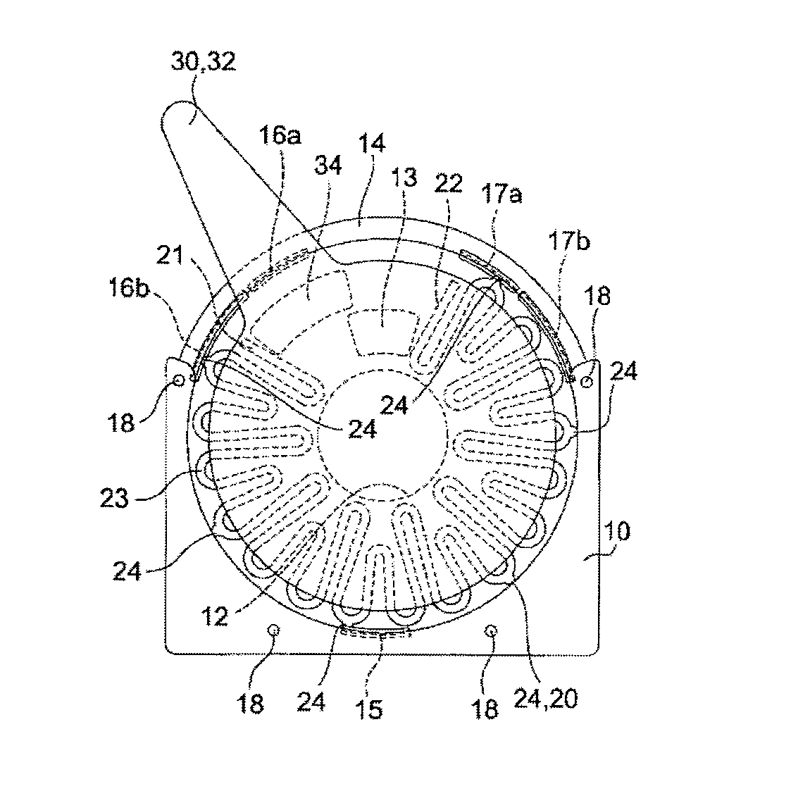
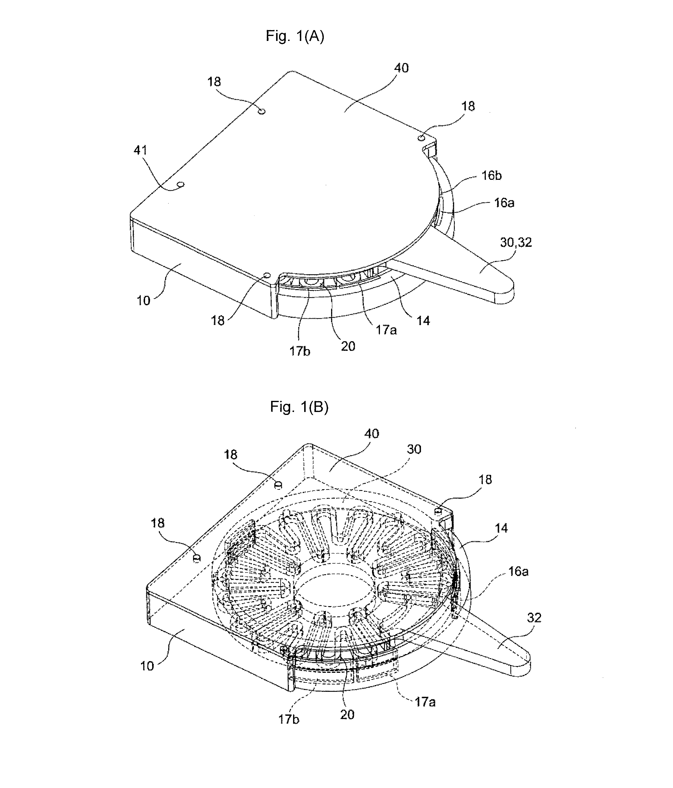
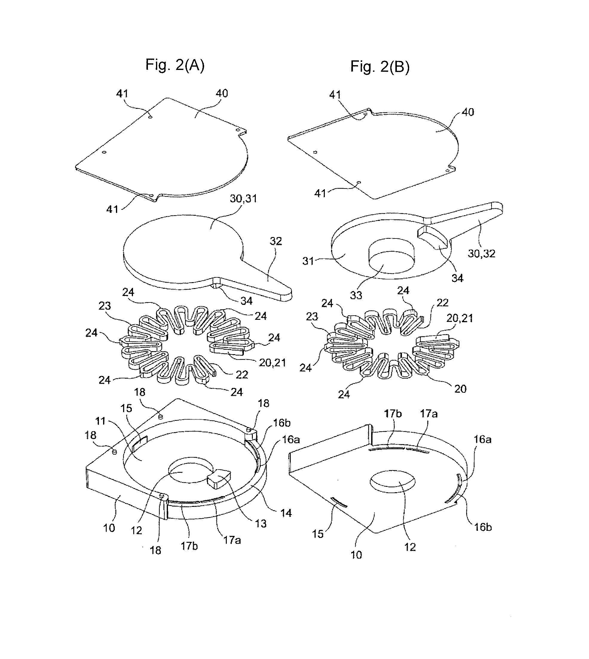
[0042]As illustrated in FIGS. 1 to 3, a switch includes a base 10, a spring body 20, an operating body 30, and a cover 40.
[0043]As illustrated in FIGS. 2A-2B, a shaft hole 12 is made in the center of a flat circular recess 11 provided in an upper surface of the base 10, and a positioning projection 13 projects near the shaft hole 12. An operating step 14 is formed along the flat circular storage recess 11 on one side of the base 10 in order to guide the operating body 30 described later. First and second switching fixed contacts 16a and 16b and third and fourth switching fixed contacts 17a and 17b are insert-molded on both sides of a central fixed contact 15 insert-molded in an inside surface of the flat circular storage recess 11.
[0044]The spring body 20 has a bellows shape in which a reference form unit 23 is constantly repeated, end portions 21 and 22 of the spring body 20 are symmetrically formed, and waveform shapes having different heights are alternately repeated in the refe...
second embodiment
[0060] the fixed contact is disposed in the bottom surface of the flat circular recess 11, so that a degree of design freedom of the terminal can be increased to facilitate optimum design of the insert molding or a die. Particularly, because the terminal is insert-molded in the bottom surface of the base, advantageously a mechanical strength is increased.
[0061]As illustrated in FIGS. 6 to 8, similarly to the first embodiment, a switch according to a third embodiment includes the base 10, the spring body 20, the operating body 30, and the cover 40.
[0062]As illustrated in FIGS. 7A-7B, the base 10 differs from that of the first embodiment in that the first and second switching fixed contacts 16a and 16b and the third and fourth switching fixed contacts 17a and 17b are bilaterally symmetrically insert-molded in the inside surface of the flat circular recess 11 of the base 10.
[0063]Similarly to the first embodiment, the spring body 20 has the bellows shape in which the reference form uni...
fourth embodiment
[0074] because the inside apex is linearly formed, the design is easily performed because of the simple shape, and the degree of design freedom is increased.
[0075]Additionally, the first and third switching fixed contacts 16a and 17a act advantageously as the common fixed contact.
[0076]Because other configurations are similar to those of the first embodiment, the same component is designated by the same numeral, and the description is neglected.
[0077]As illustrated in FIGS. 10A-10B, a switch according to a fifth embodiment differs from that of the first embodiment in the shape of the spring body 20.
[0078]The reference form unit 23 of the spring body 20 is formed into the bellows shape in which a pattern based on a straight line is repeated, and the arc elastic arms 25 and 26 extend from the apexes located near the end portions 21 and 22.
[0079]Because other configurations are similar to those of the first embodiment, the same component is designated by the same numeral, and the descr...
PUM
 Abstract
Description
Claims
Application Information
 - R&D
- Intellectual Property
- Life Sciences
- Materials
- Tech Scout
- Unparalleled Data Quality
- Higher Quality Content
- 60% Fewer Hallucinations
Browse by: Latest US Patents, China's latest patents, Technical Efficacy Thesaurus, Application Domain, Technology Topic, Popular Technical Reports.
© 2025 PatSnap. All rights reserved.Legal|Privacy policy|Modern Slavery Act Transparency Statement|Sitemap|About US| Contact US: help@patsnap.com