
Novel Door Latching System Configured For Foot Use

Inactive Publication Date: 2021-10-28
GLIXMAN SHARI +1
View PDF2 Cites 1 Cited by
  • Summary
  • Abstract
  • Description
  • Claims
  • Application Information

AI Technical Summary

Benefits of technology

The patent aims to remove the need to touch the doorknob, latch, or lever when entering or exiting a bathroom stall by using only one's foot.

Problems solved by technology

A significant difficulty is present when latching and or locking doors in various settings.
This difficulty is even more apparent in an environment where there is easily found the spread of germs, disease and bacteria.

Method used


Image

  • Novel Door Latching System Configured For Foot Use
  • Novel Door Latching System Configured For Foot Use
  • Novel Door Latching System Configured For Foot Use

Examples


Embodiment Construction

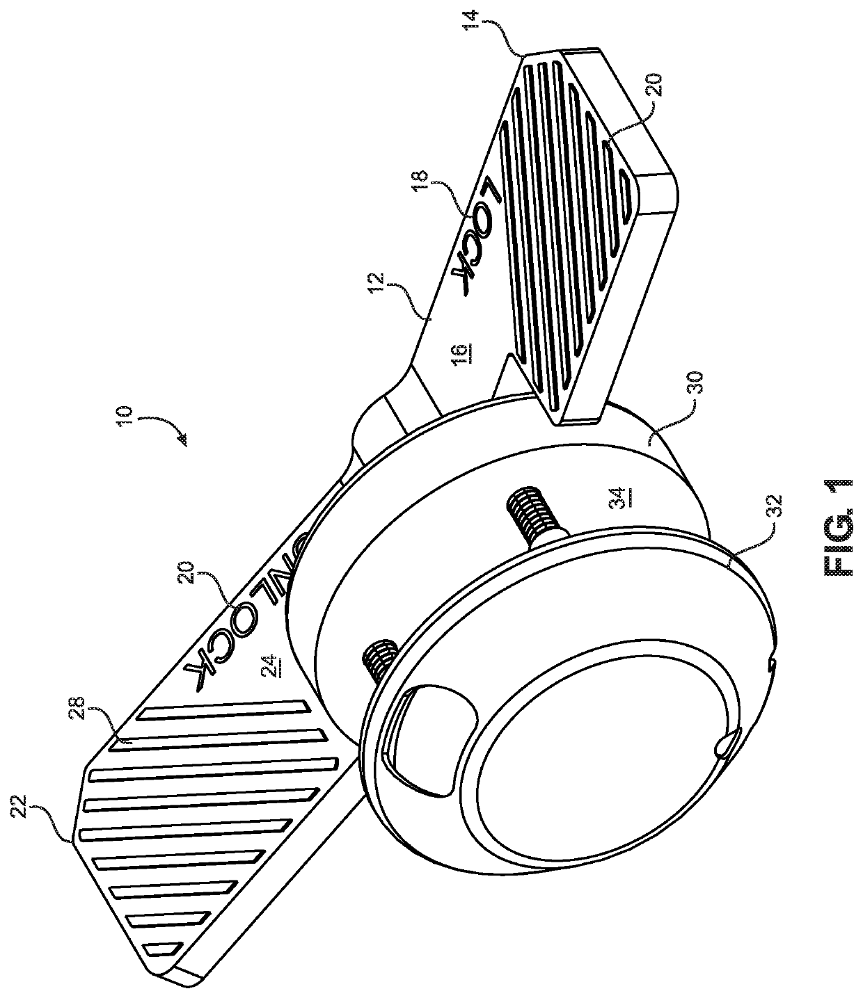
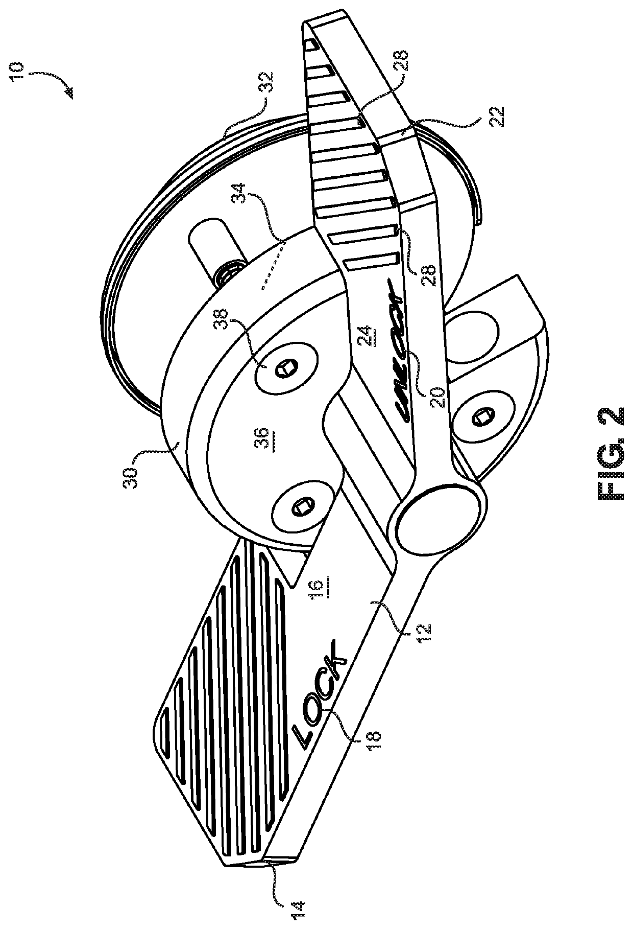
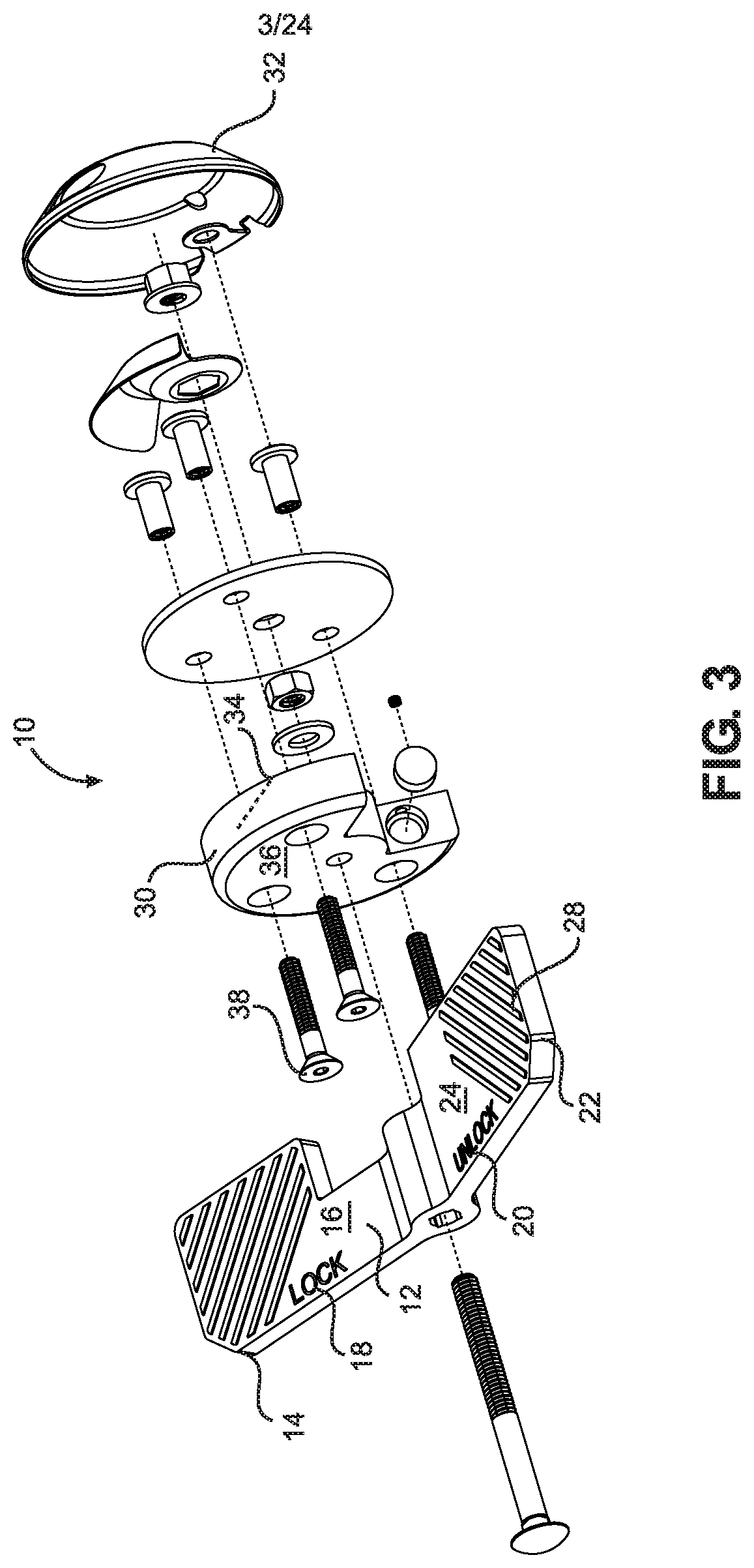
[0036]As generally understood, the system of the present invention a system 10 formed with the control bar 12. Control bar 12 is preferably a single formed piece. Control bar 12 has a first end 14 having an upper planer surface 16, indicia 18 and a plurality of protrusions 20. Control bar 12 has a second end 22 with second end upper planer surface 24 second end indicia 20 and a plurality of Second and protrusions 28. Control bar 12 interacts with proximal cap 30 in order to provide desired movement about a central axis to lock and unlock a door where system 10 is installed. Distal cap 32 encloses the components of the system as demonstrated in FIG. 3. Connecting bolts 38 ultimately attach through proximal cap 30 securing distal cap 32 into position.

[0037]As demonstrated in FIGS. 6 and 7, is attached to door 60 on anterior surface 62, first end 14 of plate 12 serves as a lock or latch by contacting inner surface 66 of wall 64. Directional arrows demonstrates a central axis formed by ...


PUM


Abstract

A door latching or locking system is provided whereby the user locks and unlocks the system using their feet.

Description

BACKGROUND OF THE INVENTION[0001]A significant difficulty is present when latching and or locking doors in various settings. This difficulty is even more apparent in an environment where there is easily found the spread of germs, disease and bacteria.[0002]One such environment is present when locking and unlocking doors in a public restroom. A user will finish using the toilet facilities and unlock the door before having opportunity to wash their hands.[0003]It is a problem that needs a simple yet effective solution.[0004]The present invention provides a solution.SUMMARY OF THE INVENTION[0005]The present invention is foot-controlled latch or lock system,[0006]In one embodiment the system is a foot stall latch configured for use in bathroom stalls and public restrooms.[0007]Although a primary intent is public restrooms, the system is contemplated as being used in homes, offices and other commercial and non-commercial venues including but not limited to pet gates, gates and interior d...

Claims


Application Information

Patent Timeline
IPC IPC(8): E05B53/00E05C3/04E05B1/00
CPCE05B53/001E05C3/041E05Y2900/112E05B1/003E05Y2900/132E05B1/0084E05C3/043E05B9/08
Inventor GLIXMAN, SHARIGLIXMAN, MOSHE SIMCHA
Owner GLIXMAN SHARI
Learn More