
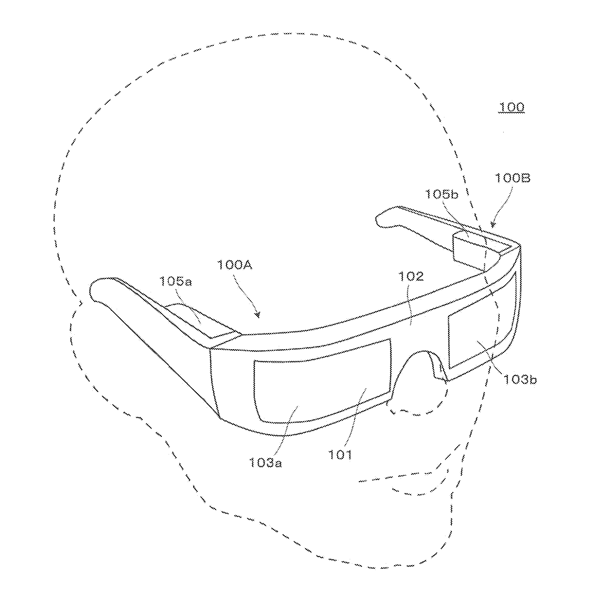
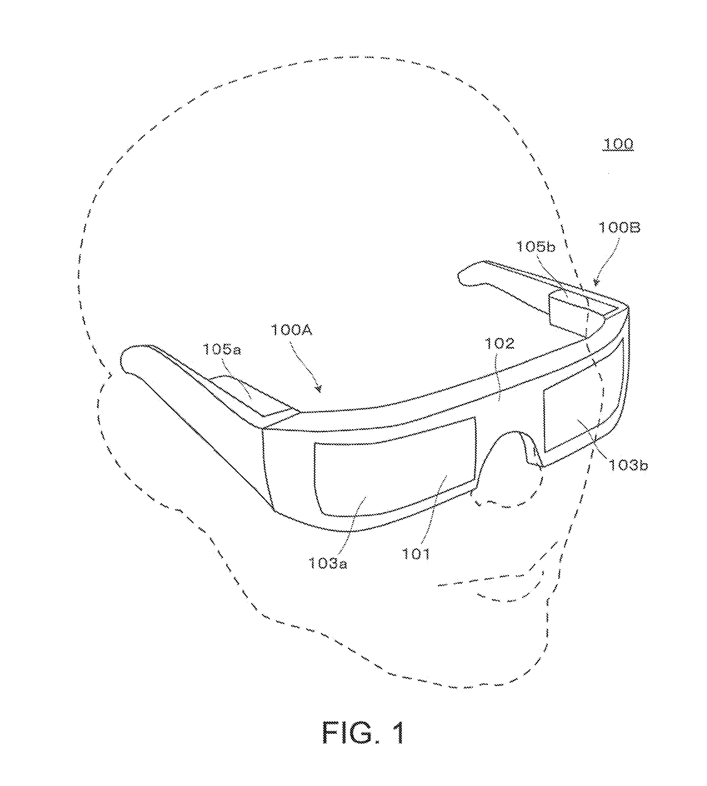
Virtual image display device

a virtual image and display device technology, applied in the field of virtual image display devices, can solve the problems of system thickness as a whole, difficulty in reducing size and weight, and inability to see the outside state of the observer, so as to achieve wide angle of view, minimize size and weight, and high function performance

Active Publication Date: 2014-08-14
SEIKO EPSON CORP
View PDF2 Cites 11 Cited by
  • Summary
  • Abstract
  • Description
  • Claims
  • Application Information

AI Technical Summary

Benefits of technology

The invention is a virtual image display device that can show an external light and an image light in a way that they overlap. It has a wide view and high performance. It is also small and lightweight.

Problems solved by technology

In addition, if a view of the observer is entirely covered such that the observer can see only the image light, the observer cannot see the outside state and may have a feeling of anxiety.
However, in a case of the optical system in Japanese Patent No. 2746697, since the projection lens is large, it is difficult to reduce the size and weight.
However, in the optical system in Japanese Patent No. 3787399, there is no consideration for the outside viewing by the observer.
However, in order for the observer to view the outside using the optical system in Japanese Patent No. 4218553, it is needed to paste a compensation lens together with the concave mirror, and accordingly, the system becomes thick as a whole.
However, in a case of the optical system in Japanese Patent No. 4819532, a convex portion of the prism center and a projection lens interfere with the view.
However, depending on the optical design, a use environment, and the like, there is a concern that the external light is reflected in an unintended direction, and a ghost light can be generated in the cuts and the joints between the curved surfaces.
When the calculated values exceed the upper limit of the condition (1), the shape becomes close to a plane, even though the problem of the external light to the observer does not exist, the aberration correction of the image light does not effectively function.
In addition, when the calculated values exceed the lower limit of the condition (1), the curvature becomes too large, it becomes difficult to correct the aberration, and the position of the prism approaches near the face and the wear is impaired.
When the calculated values exceed the upper limit of the condition (2), the astigmatism generated in the third surface becomes too large, and it becomes difficult to correct the aberration.

Method used


Image

  • Virtual image display device
  • Virtual image display device
  • Virtual image display device

Examples


application examples

[0111]Hereafter, an application example of a projection fluoroscope that is incorporated in a virtual image display device according to the invention will be described. The symbols used in each application example are summarized as follows.

SPH: pupil

FFSk: free-curved surface (k in the prism=surface number)

ASPk: Axisymmetric aspherical surface (k in the projection optical system=surface number)

SPH: spherical surface or plane (protective glass surface)

R: radius of curvature

T: axial surface distance

Nd: refractive index with respect to the line d of the optical material

Vd: Abbe number with respect to the line d of the optical material

TLY: inclination angle (°) of the optical axis in a cross-section surface (XZ section) in a specific surface (There is a case where the TLY varies at the front and back of the specific surface)

DCX: amount of shift of the optical axis in an X axis direction in a cross-section surface (XZ cross-section) in a specific surface.

application example 1

[0112]Data for optical surface that configures the prism and the projection lens of the projection fluoroscope in the application example 1 is shown in Table 1 below. Moreover, for example, FFS 1 means the first surface S11, FFS2 means the second surface S12, and FFS3 means the third surface S13. In addition, ASP1 means the emitting surface of the first lens of the projection lenses, and ASP2 means the incident surface of the first lens.

TABLE 1NoTypeRTNdVd1SPH∞22.002FFS1−98.4345.501.52555.953FFS2−42.793−5.501.52555.954FFS1−98.4349.001.52555.955FFS3−107.434−9.001.52555.956FFS1−98.4346.001.52555.957FFS4−104.477−6.001.52555.958FFS530.142−2.009ASP1−11.550−2.591.52555.9510ASP27.019−0.5011ASP35.809−1.001.58529.9012ASP424.036−12.5913ASP5−15.474−4.001.52555.9514ASP6150.859−4.5115SPH∞−1.601.45867.8216imagesurface

[0113]Regarding the optical surface of the prism that configures the application example 1, the inclination angle (tilt) TLY of the optical axis in the cross-section surface thereof,...

application example 2

[0121]Data for optical surface that configures the prism and the projection lens of the projection fluoroscope in the application example 2 is shown in Table 5 below.

TABLE 5NoTypeRTNdVd1SPH∞22.002FFS1−40.8895.001.52555.953FFS2−31.073−5.001.52555.954FFS1−40.8899.001.52555.955FFS3−42.593−9.001.52555.956FFS1−40.8896.001.52555.957FFS4−122.593−6.001.52555.958FFS5−26.417−2.009ASP1−5.981−4.501.52555.9510ASP27.011−0.8011ASP35.091−1.001.58529.9012ASP436.142−13.3213ASP5−9.304−4.001.52555.9514ASP6−23.176−13.8915SPH∞−1.441.45867.8216imagesurface

[0122]Regarding the optical surface of the prism that configures the application example 2, the inclination angle (tilt) TLY of the optical axis in the cross-section surface thereof, and the amount of shift (de-centered) DCX of the optical axis is shown in Table 6 described below.

TABLE 6NoTypeTLY (front) DCX (back)TLY (back)2FFS10003FFS2−24.5024.54FFS10005FFS30006FFS1032.5081.07FFS4−42.00−42.08FFS5000

[0123]Regarding each optical surface of the prism that...


PUM


Abstract

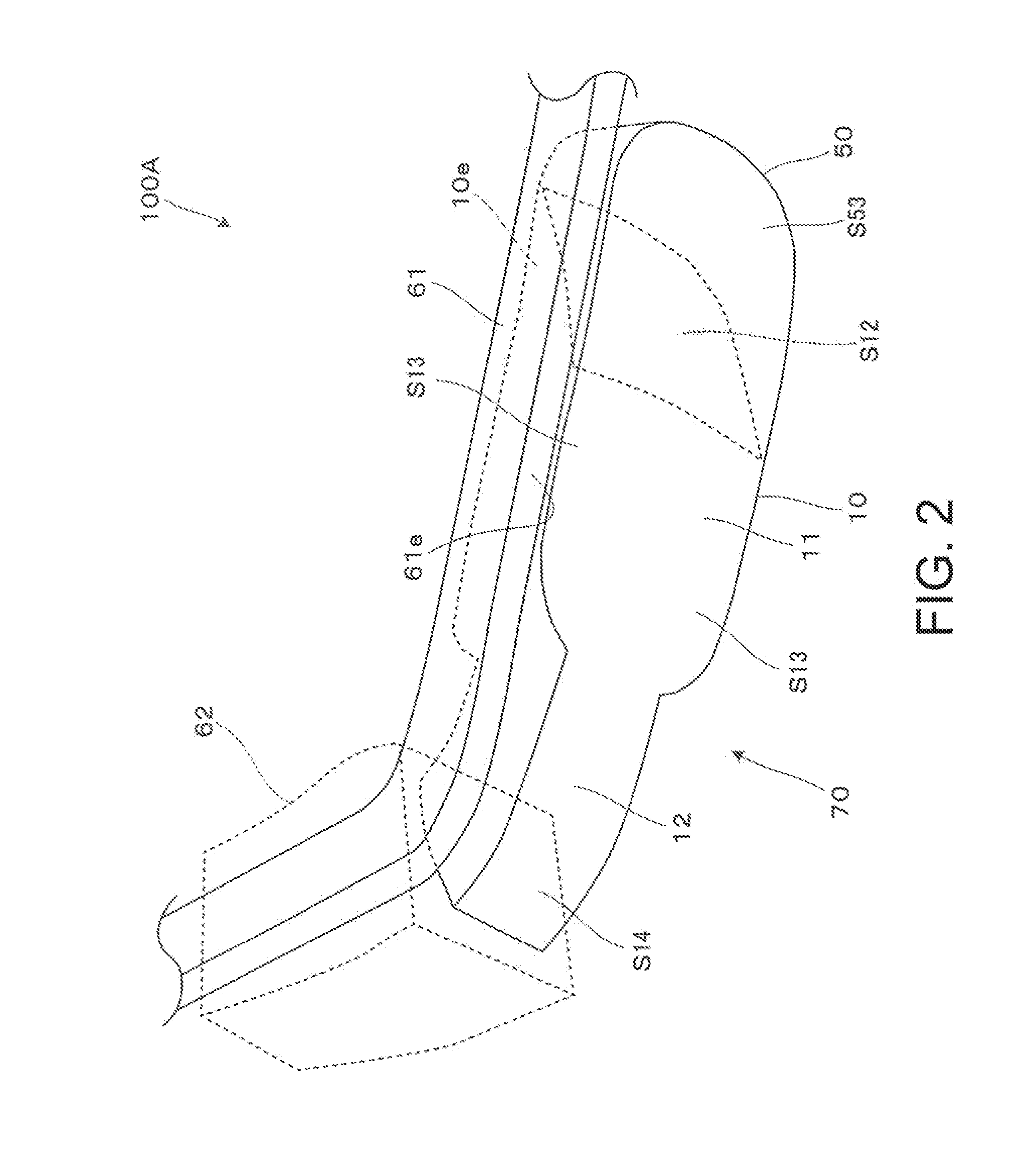
An intermediate image is formed inside the prism by a projection lens or the like, and since an image light that is totally reflected at three or more surfaces; at a third surface firstly, at a first surface firstly, at a third surface secondly, at the first surface secondly, and at the second surface in the order specified, transmits the first surface, and then arrives at an observer's eye, the size and weight of the prism can be reduced and it is possible to realize a display of high performance and brightness with a wide angle of view. In addition, since the external light can be observed after passing through the first surface and the third surface, and the visibility at that time becomes substantially zero, it is possible to reduce the defocus or distortion of the external light when observing the see-through external light.

Description

BACKGROUND[0001]1. Technical Field[0002]The present invention relates to a virtual image display device that provides an image formed by an image display element or the like to an observer, particularly to a virtual image display device that is suitable for a head-mounted display mounted on the observer's head.[0003]2. Related Art[0004]A variety of optical systems are proposed, which are incorporated into a virtual image display device such as a head mount display (hereafter, referred to as HMD) that is mounted on an observer's head (refer to Japanese Patent No. 2746697, Japanese Patent No. 3787399, Japanese Patent No. 4218553, and Japanese Patent No. 4819532).[0005]Regarding the virtual image display device such as the HMD, it is desirable to widen an angle of view and to reduce a weight of the device. Particularly, in order to improve a wear, it is important to make the device thin in thickness in a viewing axis direction of the observer and to make the center of gravity of the de...

Claims


Application Information

Patent Timeline
IPC IPC(8): G02B27/01
CPCG02B27/0172G02B17/086G02B2027/0145
Inventor KOMATSU, AKIRATOTANI, TAKAHIROTAKAGI, MASAYUKITAKEDA, TAKASHIMIYAO, TOSHIAKI
Owner SEIKO EPSON CORP
Learn More