
Method for Operating a Light-Emitting Device and Arrangement

Inactive Publication Date: 2014-08-14
NOVALED GMBH
View PDF6 Cites 3 Cited by
  • Summary
  • Abstract
  • Description
  • Claims
  • Application Information

AI Technical Summary

Benefits of technology

[0008]It is the object to specify improved driver technologies for a light-emitting device with one or a plurality of light-emitting organic diodes. It shou

Problems solved by technology

However, there are also a few fundamental differences between these types of light-emitting diodes with regards to requirements and properties.
A variation of the driver current however is not provided in commercially available LED drivers.
LED drivers can be used in principle for the operation of OLEDs, however brightness regulation by means of PWM (pulse-width modu

Method used


Image

  • Method for Operating a Light-Emitting Device and Arrangement
  • Method for Operating a Light-Emitting Device and Arrangement
  • Method for Operating a Light-Emitting Device and Arrangement

Examples


Example

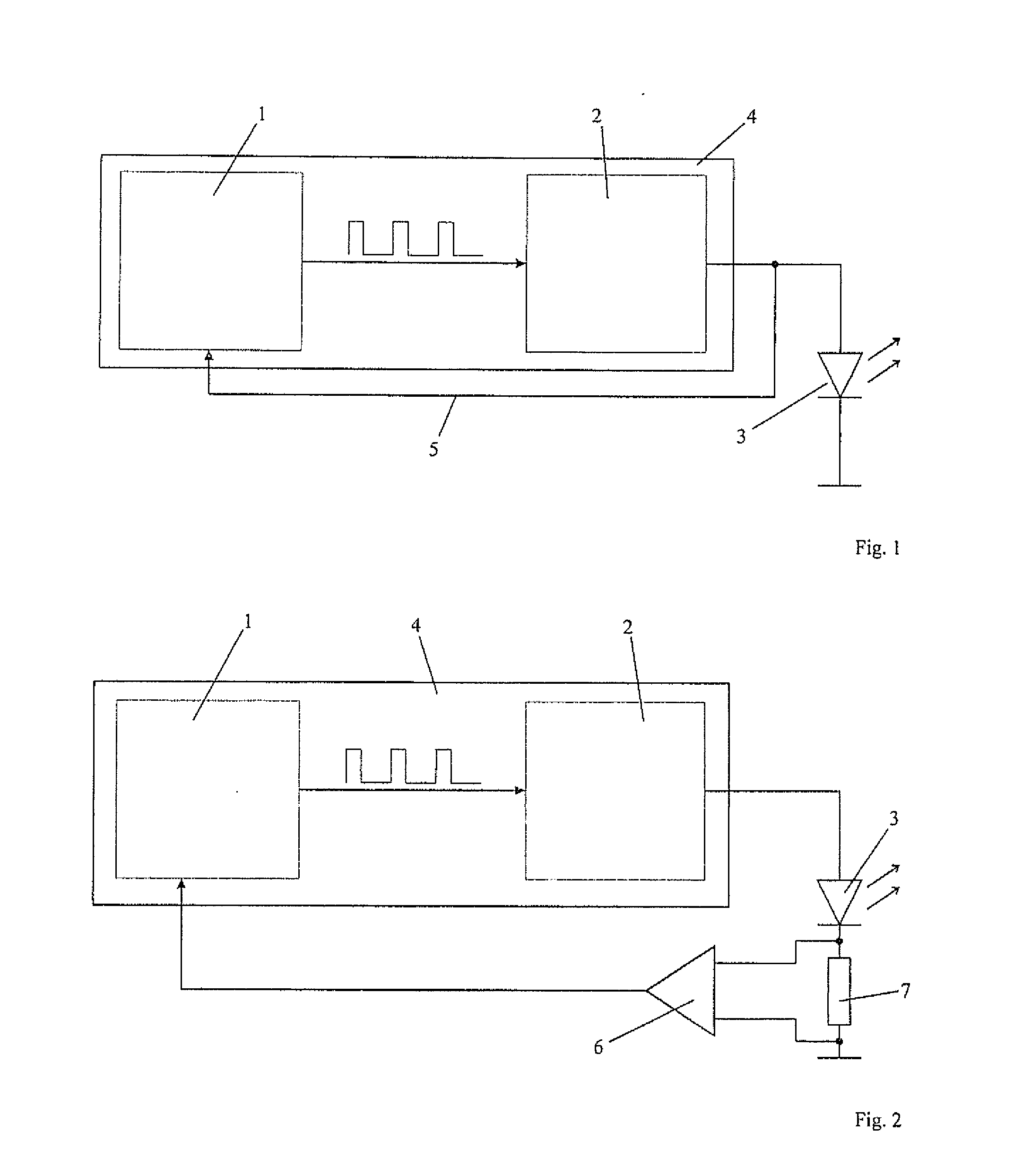
[0042]FIG. 1 shows a schematic illustration of an arrangement with a microcontroller 1 and a pulse-width controller 2, the output of which couples to an organic light-emitting diode 3. The microcontroller 1 and the pulse-width controller 2 form a driver circuit 4, using which a pulsed current is generated, which is coupled to the organic light-emitting diode 3 during operation. According to the illustration in FIG. 1, a feedback of the output of the pulse-width controller 2 to the microcontroller 1 takes place via a feedback line 5. The feedback is used for a measurement, which can be used in order to determine the capacitance or the instantaneous current.

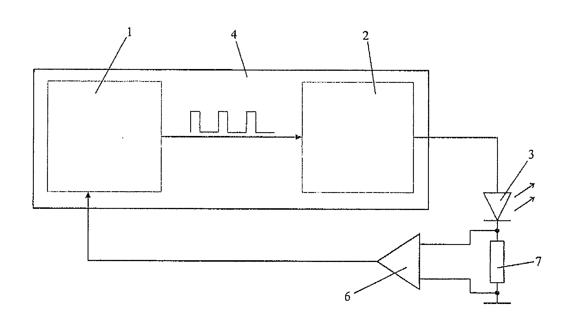
[0043]FIG. 2 shows a schematic arrangement, in which the arrangement from FIG. 1 is augmented by a measuring circuit 6, using which an average current is measured at the organic light-emitting diode 3 during operation, in that the average current is tapped via a resistor 7. The measuring apparatus 6 couples, just like the feedback ...


PUM


Abstract

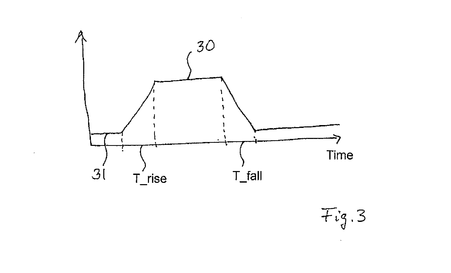
An arrangement and method is provided for operating a light-emitting device, wherein, a pulsed current is generated with a pulse frequency by a driver circuit, which has a clock pulse generator providing clock pulse signals for current pulsing, and a light-emitting device, which functionally couples to the driver circuit and which is formed with one or a plurality of organic light-emitting diodes, is loaded with the pulsed current with a pulse frequency of approximately 10 kHz to approximately 100 kHz, wherein: T_PWM<(T_rise+T_fall) and wherein T_PWM indicates the pulse length for the clock pulse signals generated by the clock pulse generator of the driver circuit and T_rise and also T_fall indicate the pulse rise time and the pulse fall time for the current pulses present at the one or the plurality of organic light-emitting diodes.

Description

FIELD OF THE INVENTION[0001]The invention relates to a method for operating a light-emitting device, which is formed with one or a plurality of organic light-emitting diodes, and also an arrangement with such a device.BACKGROUND[0002]Light-emitting devices of this type can be used in different design variants, which include light-emitting devices constructed as illumination apparatus in particular. Organic light-emitting diodes (OLEDs) are becoming more and more important in this context. Similarly to inorganic light-emitting diodes (LEDs) OLEDs are controlled in a current-driven manner. However, there are also a few fundamental differences between these types of light-emitting diodes with regards to requirements and properties. This is the reason why specifically set-up driver apparatuses are necessary for light-emitting devices with organic light-emitting diodes.[0003]LEDs are usually operated by means of a pulsed current, wherein the brightness of the LEDs is controlled by means ...

Claims


Application Information

Patent Timeline
IPC IPC(8): H05B33/08H05B44/00
CPCH05B33/0896H05B45/60Y02B20/30
Inventor COYM, TORSTENMURANO, SVENLANGGUTH, OLIVER
Owner NOVALED GMBH
Learn More