
Electric power distribution system including metering function and method of evaluating energy metering

a technology of energy metering and electric power distribution, applied in the direction of power supply testing, process and machine control, instruments, etc., can solve the problems of inability to accurately calculate actual electricity usage, large deployments of metering devices of most utilities, and inability to meet the needs of electricity distribution,

Active Publication Date: 2014-07-31
EATON INTELLIGENT POWER LTD
View PDF11 Cites 53 Cited by
  • Summary
  • Abstract
  • Description
  • Claims
  • Application Information

AI Technical Summary

Benefits of technology

The patent describes an electric power distribution system that can efficiently distribute electricity from a power source to multiple devices. The system includes a first device that exchanges electric power with the source and meters the energy it exchanges with other devices. These other devices then use the electricity to power their loads. A processor compares the energymetered from the first device with the energy meters from each of the other devices. This comparison allows the system to determine if it is operating properly. The technical effect of this system is that it provides a more efficient and accurate way to distribute electricity to multiple devices.

Problems solved by technology

Also, a mechanism needs to be provided to protect against theft of power or, otherwise, improper or inadvertent bypassing or tampering of the meter, which results in inaccurate billing of actual electricity usage.
This is clearly a better practice for the utility and its customers, however, meter deployments of most utilities are simply too large for this type of testing to be practical.
However, California has a counter-intuitive, tiered approach to selling electricity.
This creates a dilemma EVs put customers in a higher tier of electric prices, but help to reduce emissions and clean the air.
As EV and other “special loads” (e.g., on-site solar and wind generation; distributed energy storage; intelligent appliances) are added to a premise, it makes the utility's current methodologies for metering less effective and less beneficial to both the utility and the consumer.

Method used


Image

  • Electric power distribution system including metering function and method of evaluating energy metering
  • Electric power distribution system including metering function and method of evaluating energy metering
  • Electric power distribution system including metering function and method of evaluating energy metering

Examples


example 1

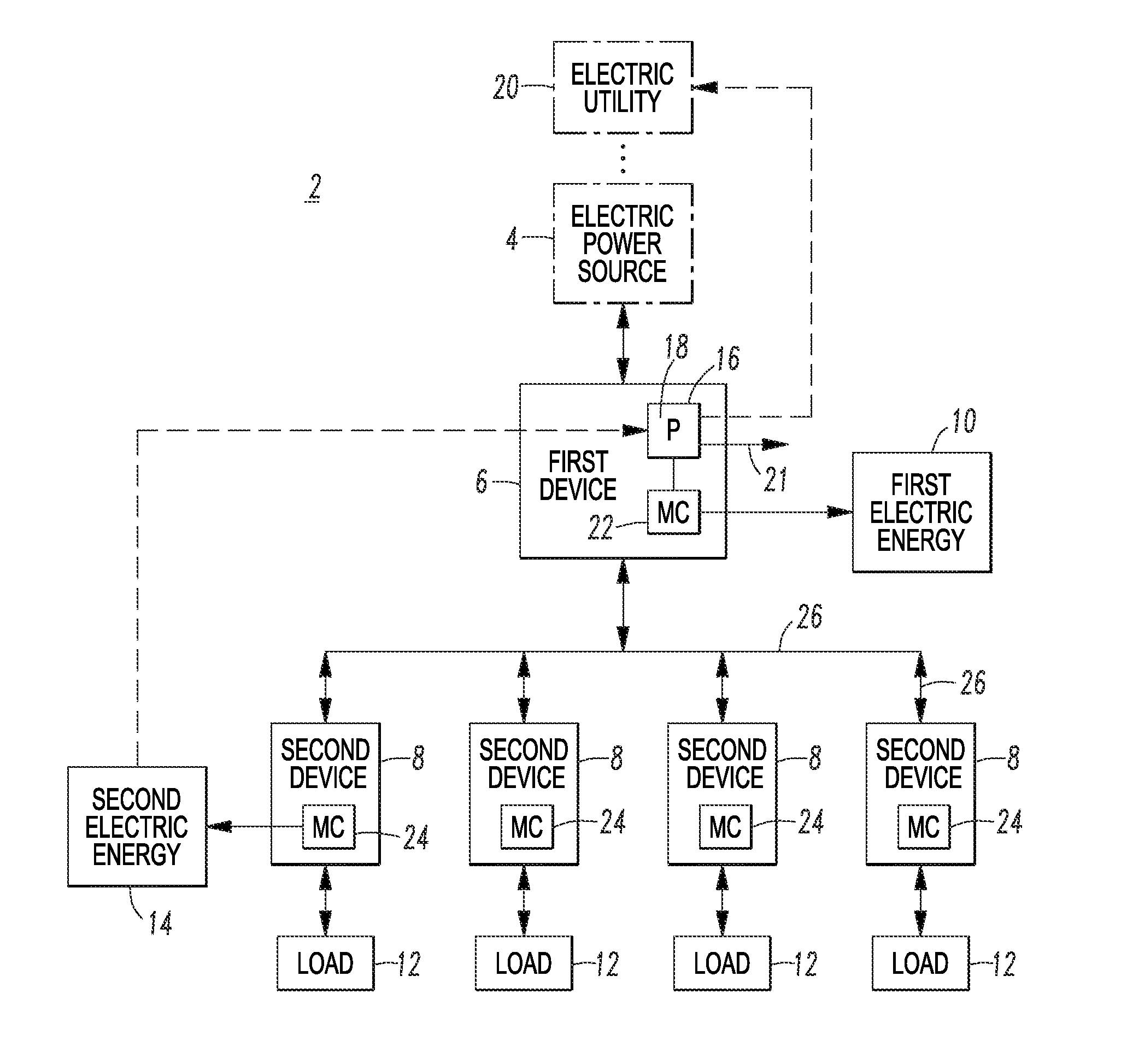
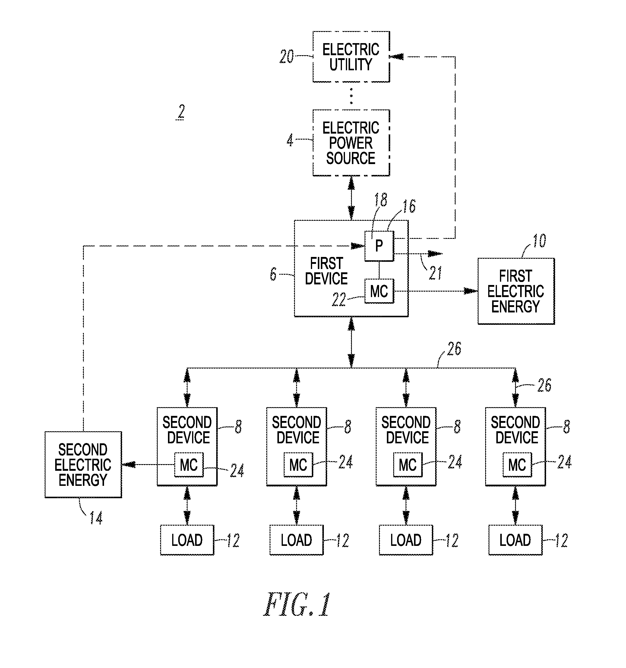
[0038]The routine 18 is further structured to notify an electric utility 20 corresponding to the electric power source 4 responsive to the determined improper operation.

example 2

[0039]Each of the first device 6 and the second devices 8 includes a metering circuit (MC) 22 and 24, respectively.

example 3

[0040]The routine 18 is further structured to adjust the compare for at least one of energy losses in power conductors 26 operatively associated with the second devices 8, and expected errors in the metering circuits 22,24.


PUM


Abstract

An electric power distribution system is used with an electric power source. The electric power distribution system includes a first device exchanging first electric power with the electric power source. The first device exchanges the first electric power with a plurality of second devices and meters first electric energy corresponding to the first electric power. The second devices exchange the first electric power with the first device. Each of the second devices exchanges second electric power as at least part of the first electric power with a number of corresponding electric loads and meter second electric energy corresponding to the second electric power. A processor includes a routine that compares the metered first electric energy from the first device with a sum of the metered second electric energy from each of the second devices, and responsively determines proper or improper operation of the electric power distribution system.

Description

CROSS-REFERENCE TO RELATED APPLICATION[0001]This application is related to commonly assigned, copending U.S. patent application Ser. No. ______, filed ______, entitled “Annunciating or Power Vending Circuit Breaker for an Electric Load” (Attorney Docket No. 12-EDP-088).BACKGROUND[0002]1. Field[0003]The disclosed concept pertains generally to electric power distribution and metering and, more particularly, to electric power distribution systems that meter electric energy. The disclosed concept further pertains to methods of evaluating energy metering of an electric power distribution system.[0004]2. Background Information[0005]Meters are used by electric utilities to measure and bill for electricity usage. Typically, meters need to be accessible, replaceable, testable and tamper-resistant. Meters need to be accessible and readable by both the utility and its customers to ensure correct meter readings. Meters need to be replaceable in the event of a malfunction, and testable to verify...

Claims


Application Information

Patent Timeline
Patent Type & Authority Applications(United States)
IPC IPC(8): G01R31/40H02H7/22
CPCH02H7/22G01R31/40G01D4/002G01D2204/22H02J13/00H02S50/10H02J13/00034H02J2310/64Y02B70/3225Y02E10/50Y04S20/222Y04S50/10Y02B70/34Y02B90/20Y04S20/30
Inventor ELDRIDGE, DAVID AUSTINTHOMPSON, RONALD L.ROGERS, BRANDON J.MUELLER, MAXIMILIAN A.
Owner EATON INTELLIGENT POWER LTD
Learn More