
Connector system

a technology of connecting devices and connectors, applied in the direction of coupling device details, line connector maintenance, coupling device connection, etc., can solve the problems of contaminating the conductor surface, and affecting the service life of the connection

Active Publication Date: 2014-07-31
TYCO ELECTRONICS LOGISTICS AG (CH)
View PDF9 Cites 16 Cited by
  • Summary
  • Abstract
  • Description
  • Claims
  • Application Information

AI Technical Summary

Benefits of technology

The patent text describes a connector system that includes a pass-through connector and a plug. The pass-through connector has a housing with a front and a rear, and conductors that are held by the housing in a cavity between the front and rear openings. The plug has a contact holder with a head that pushes contaminants from the cavity through the rear opening as it is loaded into the cavity. This mechanism helps to keep the connector system clean and free from contaminants. The technical effect of this design is to provide a more reliable and reliable connection between electrical devices.

Problems solved by technology

Known connectors are not without problems.
For example, in some environments, such as when the connectors are being used outside or in other harsh environments, contaminants like dirt, mud, grease, and sand, and fluids like water and oil may get trapped within the receptor connector.
Contaminants within housings can contaminate the conductor surface between conductors, at the least interrupting the connection and potentially permanently damaging the connectors themselves.
Removal of the contaminants is difficult and time consuming.
Some contaminants may be permanently trapped beneath the conductors.

Method used


Image

  • Connector system
  • Connector system
  • Connector system

Examples


Embodiment Construction

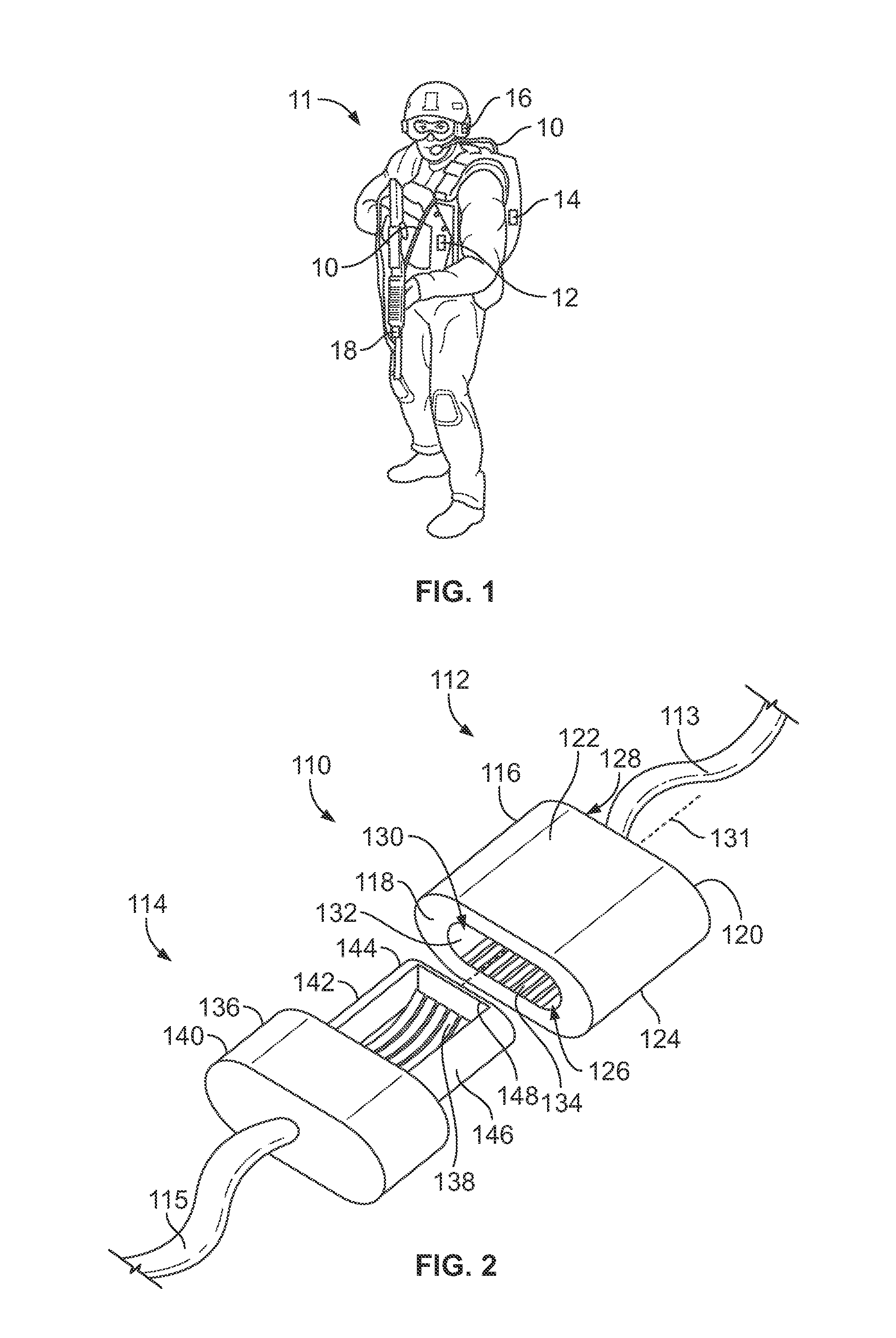
[0015]FIG. 1 illustrates a connector system 10 formed in accordance with an exemplary embodiment and used to electrically connect various equipment carried by a user 11, such as a military soldier. The connector system 10 provides the user 11 with releasable connections between the equipment that is configured to withstand exposure to contaminants such as dirt, mud, and sand. In an exemplary embodiment, the connector system 10 uses pass through connectors that allow contaminants to be easily cleared from the connectors.

[0016]The connector system 10 may include e-textiles or fabrics that enable computing, digital components and / or electronics to be embedded therein. The e-textiles may be incorporated into wearable articles, such as vests, shirts, pants, backpacks, and the like, that incorporate built-in technological elements into the fabric of the garment, in pockets of the garment or attached to the inside or outside of the garment.

[0017]The connector system 10 is used to interconn...


PUM


Abstract

A connector system includes a pass-through connector that includes a housing with a front and a rear opposite the front. The front of the housing has a front opening, and the rear of the housing has a rear opening. The housing also has a cavity between the front opening and the rear opening. The pass-through connector also includes conductors which are held by the housing in the cavity. The system also includes a plug that is received in the cavity through the front opening. The plug has a contact holder that holds plug conductors. The contact holder has a head that is received in the cavity, and the head is configured to push contaminants from the cavity through the rear opening as the plug is loaded into the cavity.

Description

BACKGROUND OF THE INVENTION[0001]The subject matter herein relates generally to a connector system.[0002]Connectors are commonly used to interconnect electrical components together. For example, connectors are sometimes used to communicatively couple two printed circuits (sometimes referred to as “circuit boards”) together. To interconnect the printed circuits, a connector of one of the components is mated with a connector of the other component. Other systems use a connector to connect a cable to a printed circuit or to another connector at an end of another cable. As the connectors are mated together, the connectors communicate with each other. Connectors may communicate with each other by mechanical connection through electrical contacts, mechanical connection using fiber optics, wireless signal transmission, and the like.[0003]The connectors typically include a plug and a receptacle. The plug and receptacle connectors hold the conductors in housings. The receptacle connectors ha...

Claims


Application Information

Patent Timeline
IPC IPC(8): H01R13/46
CPCH01R13/46H01R13/5219H01R13/5227H01R13/6275H01R13/633H01R24/62H01R43/002H01R2107/00A41D1/005
Inventor THACKSTON, KEVIN MICHAELTSANG, ALBERTMULFINGER, ROBERT NEIL
Owner TYCO ELECTRONICS LOGISTICS AG (CH)
Learn More