
Raisable-lowerable member for crane

a technology of cranes and lower parts, which is applied in the direction of cranes, etc., can solve the problems of difficult detachment and reattachment of the upper slewing body and the mast, and take a lot of time, and achieve the effect of reducing time and reducing labor intensity

Active Publication Date: 2014-07-31
KOBELCO CONSTR MASCH CO LTD
View PDF11 Cites 1 Cited by
  • Summary
  • Abstract
  • Description
  • Claims
  • Application Information

AI Technical Summary

Benefits of technology

The present invention provides a raisable-lowerable member for a crane that allows for faster assembly and disassembly of the crane. This member includes a boom and a mast that can raise and lower the boom. This invention results in a faster and more efficient crane.

Problems solved by technology

Thus detaching and re-attaching the upper slewing body and the mast are not easy, involving a problem of taking a lot of time for operations for assembling and disassembling of the crane.

Method used


Image

  • Raisable-lowerable member for crane
  • Raisable-lowerable member for crane
  • Raisable-lowerable member for crane

Examples


first embodiment

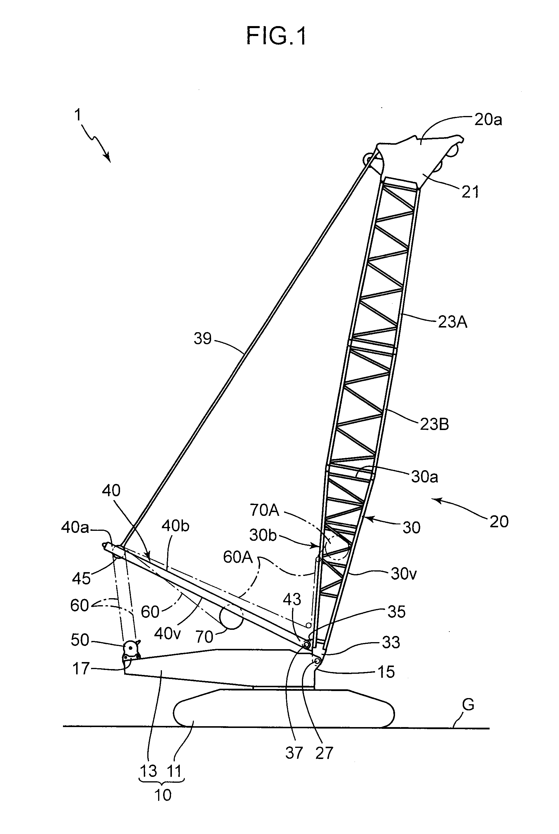
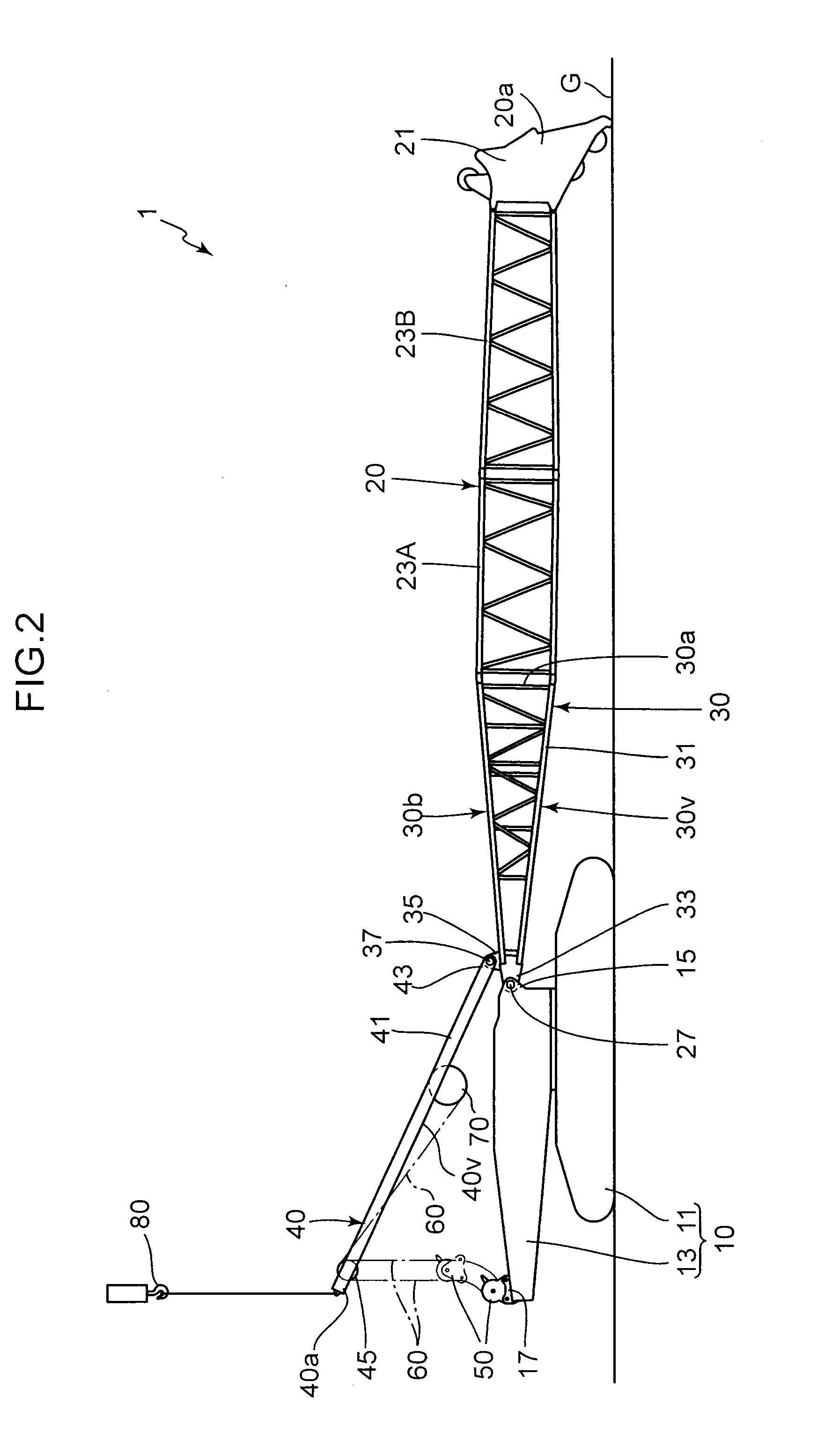
[0018]With reference to FIGS. 1 to 5 will be described a crane according to the present invention.

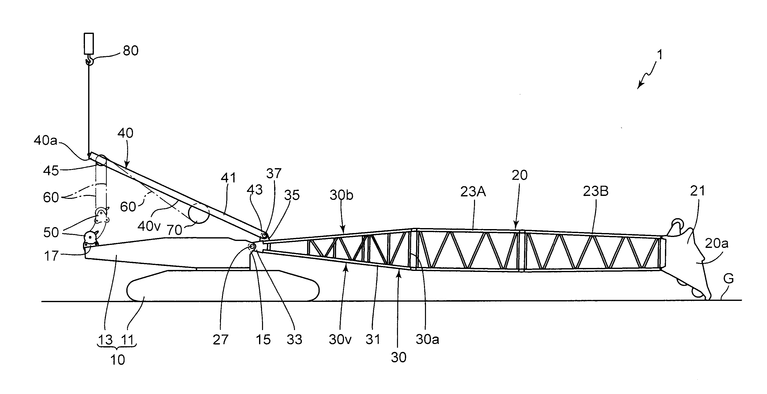
[0019]FIGS. 1 to 3 show a crane 1, which is a construction machine for a construction working or the like, such as a mobile crane. The crane 1 comprises a crane main body 10, a boom 20, a guy line 39, a mast 40, an upper spreader 45, a lower spreader 50, a rope 60, and a winch 70.

[0020]The crane main body 10 comprises a lower traveling body 11 and an upper slewing body 13. The lower traveling body 11 is a section capable of travelling on the ground G. Although the lower traveling body 11 shown in FIG. 1 is a crawler type, a lower traveling body for use in the present invention may be a wheel type.

[0021]The upper slewing body 13 is installed on the lower traveling body 11 so as to be slewable. The upper slewing body 13 includes a boom mounting bracket 15 and a lower-spreader mounting bracket 17. In the following description, as viewed in a longitudinal direction of the upper slewing body...

third embodiment

[0078]It is to be understood that the present invention is not limited to the above embodiments, but various changes and modifications may be made therein. For example, a sequence of the above steps may be appropriately changed. As one example, in the third embodiment shown in FIG. 8, the intermediate boom members 23A, 23B are separated from the lower boom member 30 in [Step 3-h1], and then the lower boom member 30 is separated from the upper slewing body 13; this sequence however may be reversed.

[0079]As mentioned above, the present invention provides a raisable-lowerable member for a crane which includes a boom and a mast for raising and lowering the boom and makes it possible to shorten a time required for assembling and disassembling of the crane, and a crane comprising the raisable-lowerable member.

[0080]Provided by the present invention is a raisable-lowerable member to be attached to an upper slewing body of a crane in a raisable and lowerable manner, the raisable-lowerable m...


PUM


Abstract

Provided are a raisable-lowerable member capable of shortening a time required for assembling and disassembling of a crane, and a crane comprising the raisable-lowerable member. The raisable-lowerable member comprises: a boom attachable to an upper slewing body of the crane turnably about a boom-pivot-turn-axis in a raising-lowering direction; and a mast to be driven so as to be turned about a mast pivot-turn-axis parallel to the boom-pivot-turn-axis. The boom includes a boom body, a boom foot joined to a basal end of the boom body and adapted to be attached to the upper slewing body turnably about the boom-pivot-turn-axis, and a mast mounting portion joined to the basal end of the boom body. The mast has a basal end which includes a mast foot to be attached to the mast mounting portion turnably about the mast pivot-turn-axis.

Description

BACKGROUND OF THE INVENTION[0001]1. Field of the Invention[0002]The present invention relates to a raisable-lowerable member for a crane, including a boom.[0003]2. Description of the Background Art[0004]A conventional crane comprises: an upper slewing body constituting a crane main body; a boom pivot turnably attached to the upper slewing body so as to be able to be raised and lowered; and a mast attached to the upper slewing body pivot turnably about an axis parallel to a pivot-turn-axis of the boom, wherein a distal end of the boom and a distal end of the mast are joined together via a guy line to turn the boom in a raising-lowering direction in interlocking relation with the turning of the mast, as disclosed, for example, JP 2010-195542A (hereinafter referred to as “Patent Document 1”) and JP 2010-18355A (hereinafter referred to as “Patent Document 2”).[0005]In this type of crane, during disassembling of the crane for transportation, there can be a case of not only detaching the ...

Claims


Application Information

Patent Timeline
Patent Type & Authority Applications(United States)
IPC IPC(8): B66C23/36
CPCB66C23/365
Inventor OTSUKA, HIROYUKI
Owner KOBELCO CONSTR MASCH CO LTD
Learn More