
Electronic device

a technology of electronic devices and wind scoopers, which is applied in the field of electronic devices, can solve the problems of assembly line workers not being able to check, damage these parts, and heat convection efficiency in the enclosure, and achieve the effect of improving the stability of the wind scooper

Inactive Publication Date: 2014-05-15
INVENTEC PUDONG TECH CORPOARTION +1
View PDF4 Cites 2 Cited by
  • Summary
  • Abstract
  • Description
  • Claims
  • Application Information

AI Technical Summary

Benefits of technology

The invention is about an electronic device that improves the stability of a wind scooper. The wind scooper is designed to be easily assembled and disassembled without a tool. The electronic device includes a heat dissipation module and a wind scooper with a positioning component. The wind scooper is fixed on the heat dissipation module through the positioning components, ensuring stability and preventing the wind scooper from causing damage during transportation. The invention aims to improve the stability of the wind scooper, making it more durable and reliable.

Problems solved by technology

In order to dissipate the heat absorbed by the heat dissipation modules fully out of the enclosure, the efficiency of heat convection in the enclosure is also one of problems worthy of attention.
Therefore, a conventional wind scooper is often directly placed in the interior of the server, so that an assembly line worker cannot check whether the wind scooper is precisely installed in place, and the wind scooper is not fixed in the interior of the server.
In such a way, during the transportation process of the server, the wind scooper may easily move relative to other parts and thus damage these parts.

Method used


Image

  • Electronic device
  • Electronic device
  • Electronic device

Examples


Embodiment Construction

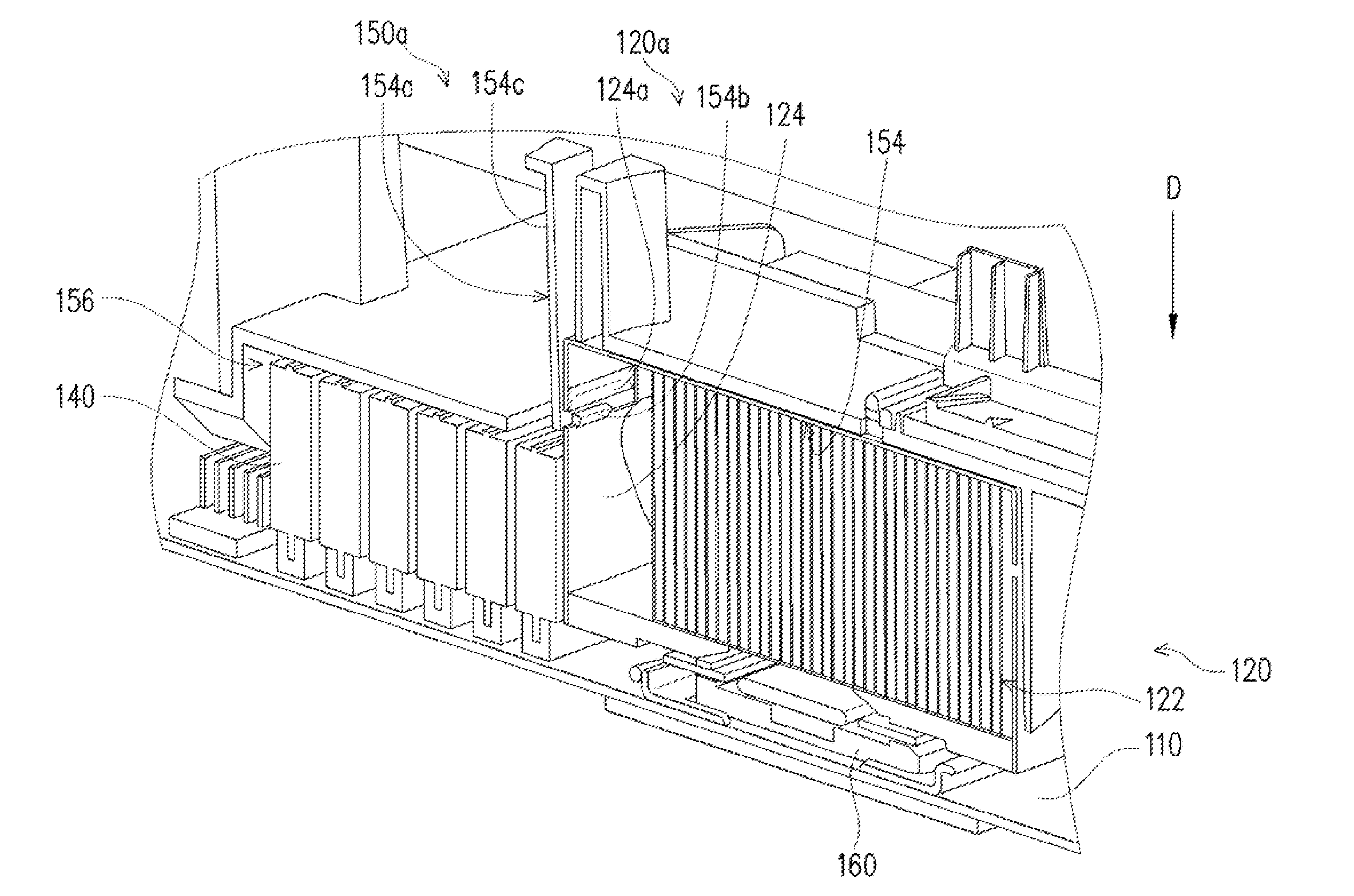
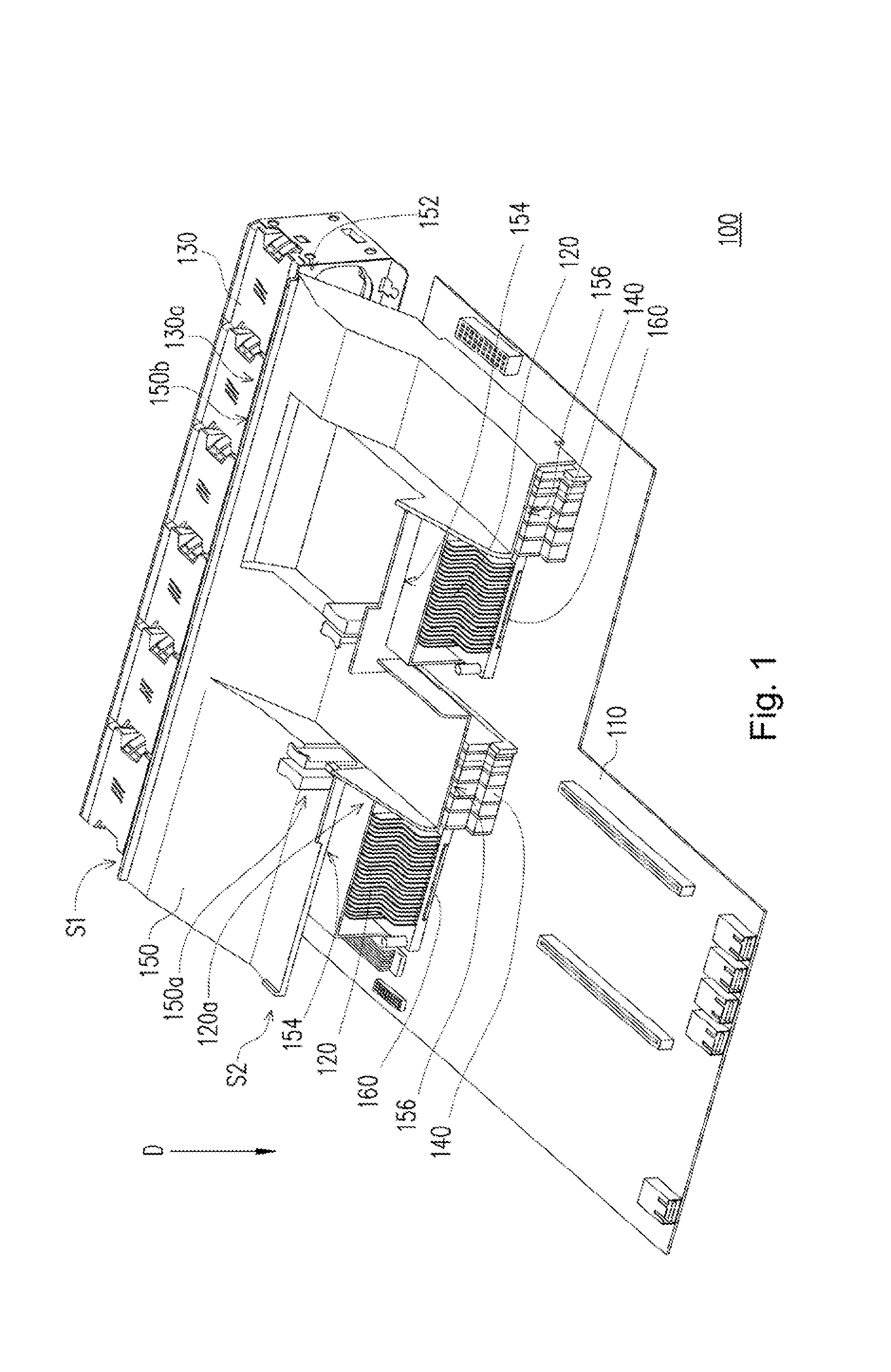
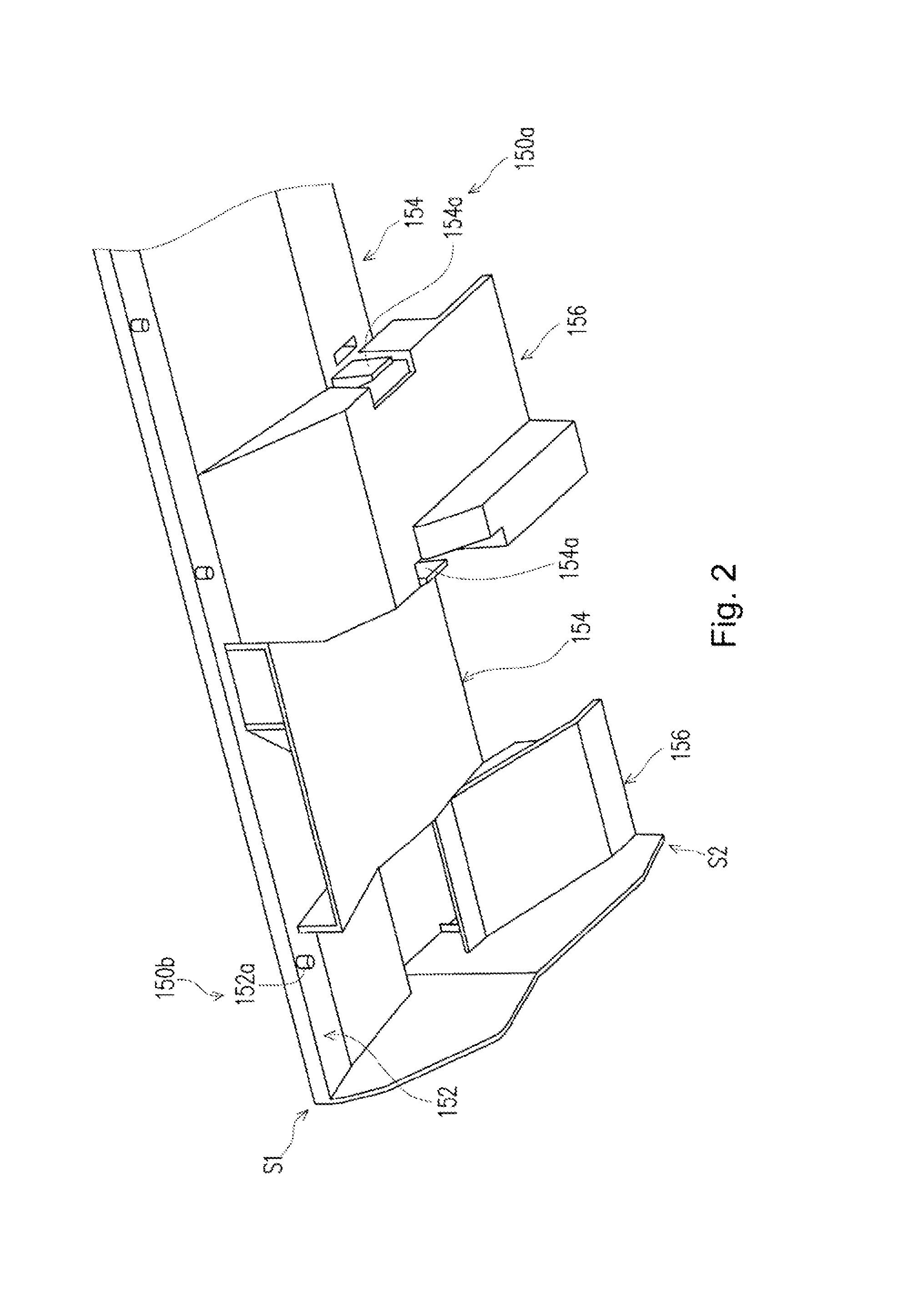
[0027]FIG. 1 is a schematic diagram of an electronic device according to an embodiment of the present disclosure. Referring to FIG. 1, in this embodiment, the electronic device 100 includes a motherboard 110, two heat dissipation modules 120, a fan module 130, two memory modules 140 and a wind scooper 150. The electronic device 100, for example, is a server, but the type of the electronic device 100 is not limited to this in the present disclosure.

[0028]The heat dissipation modules 120 are arranged on the motherboard 110. The memory modules 140 are arranged on the motherboard 110 and located on one side of the heat dissipation modules 120. The fan module 130 is arranged on one side of the motherboard 110 and faces the heat dissipation modules 120 and the memory modules 140. Since the number of the heat dissipation modules 120 and that of the memory modules 140 are respectively two, the dissipation modules 120 and the memory modules 140 of this embodiment are arranged on the motherbo...


PUM


Abstract

An electronic device includes a motherboard, at least one heat dissipation module, a fan module and a wind scooper. The heat dissipation module is arranged on the motherboard and provided with a first positioning component. The fan module is arranged on one side of the motherboard and faces the heat dissipation module. The wind scooper has a second positioning component corresponding to the first positioning component. The wind scooper is fixed on the heat dissipation module through the cooperation between the first positioning component and the second positioning component. The wind scooper is connected between the fan module and the heat dissipation modules, so that the airflow provided by the fan module can flow through the heat dissipation module.

Description

RELATED APPLICATIONS[0001]This application claims priority to China Application Serial Number 201210448844.3, filed Nov. 12, 2012, which is herein incorporated by reference.BACKGROUND[0002]1. Technical Field[0003]The present disclosure relates to an electronic device, and more particularly relates to a server.[0004]2. Description of Related Art[0005]In recent years, with the rapid development of science and technology, the operation speed of an electronic device is being constantly increased. Additionally, with the efficiency improvement of the electronic device, the heating power of electronic parts of the electronic device is also constantly increased. In order to prevent the temporary or permanent failure of the electronic parts due to overheat, the electronic device should provide the electronic parts with sufficient heat dissipation efficiency. Therefore, for the electronic parts with high heating power (such as a central processing unit or graphics chip and the like), generall...

Claims


Application Information

Patent Timeline
Patent Type & Authority Applications(United States)
IPC IPC(8): G06F1/20
CPCG06F1/20H05K7/20145H05K7/20727
Inventor CHEN, JINGCHEN, CHIEN-LUNG
Owner INVENTEC PUDONG TECH CORPOARTION
Learn More