
Emergency Back-Up Power System For Traction Elevators

Active Publication Date: 2014-07-31
REYNOLDS & REYNOLDS ELECTRONICS
View PDF9 Cites 23 Cited by
  • Summary
  • Abstract
  • Description
  • Claims
  • Application Information

AI Technical Summary

Benefits of technology

The present invention provides a way to create a pure three-phase sine wave output for elevator control by using microprocessor-based control of pulse width modulation. This means that accurate sine waves can be generated while minimizing voltage on the high-voltage DC bus. Additionally, the invention includes a back-up power system for a traction elevator that can recognize a loss of input power supply or irregularities in the power supply and quickly provide back-up power to ensure safe operation of the elevator. The inverter timing system includes a job cycle lockout timer and a main power lockout timer to ensure proper operation and prevent simultaneous operation of the back-up power system and normal control power.

Problems solved by technology

Thus, a traction elevator will tend to drift up or down depending on this imbalance.

Method used


Image

  • Emergency Back-Up Power System For Traction Elevators
  • Emergency Back-Up Power System For Traction Elevators
  • Emergency Back-Up Power System For Traction Elevators

Examples


Embodiment Construction

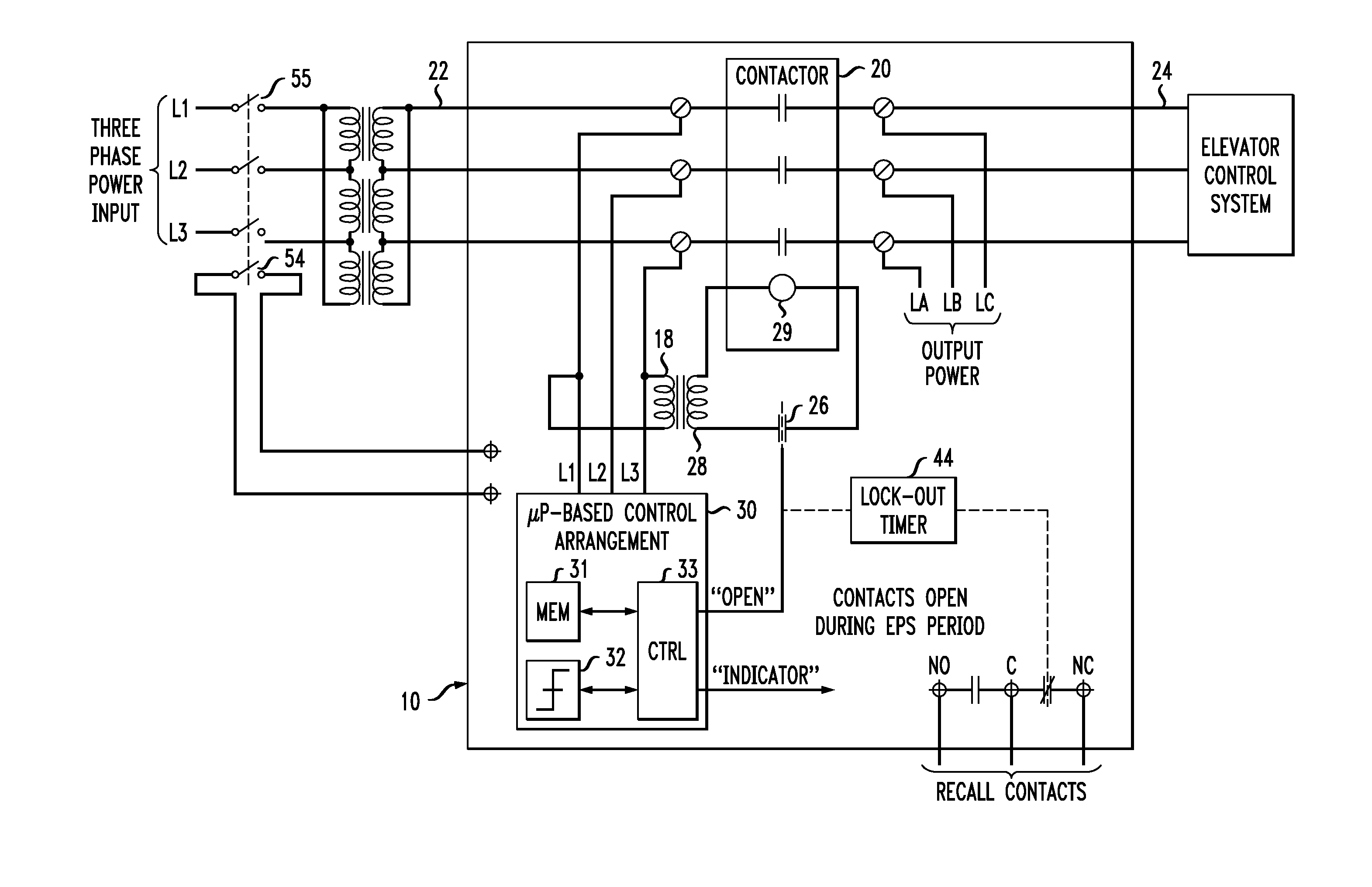
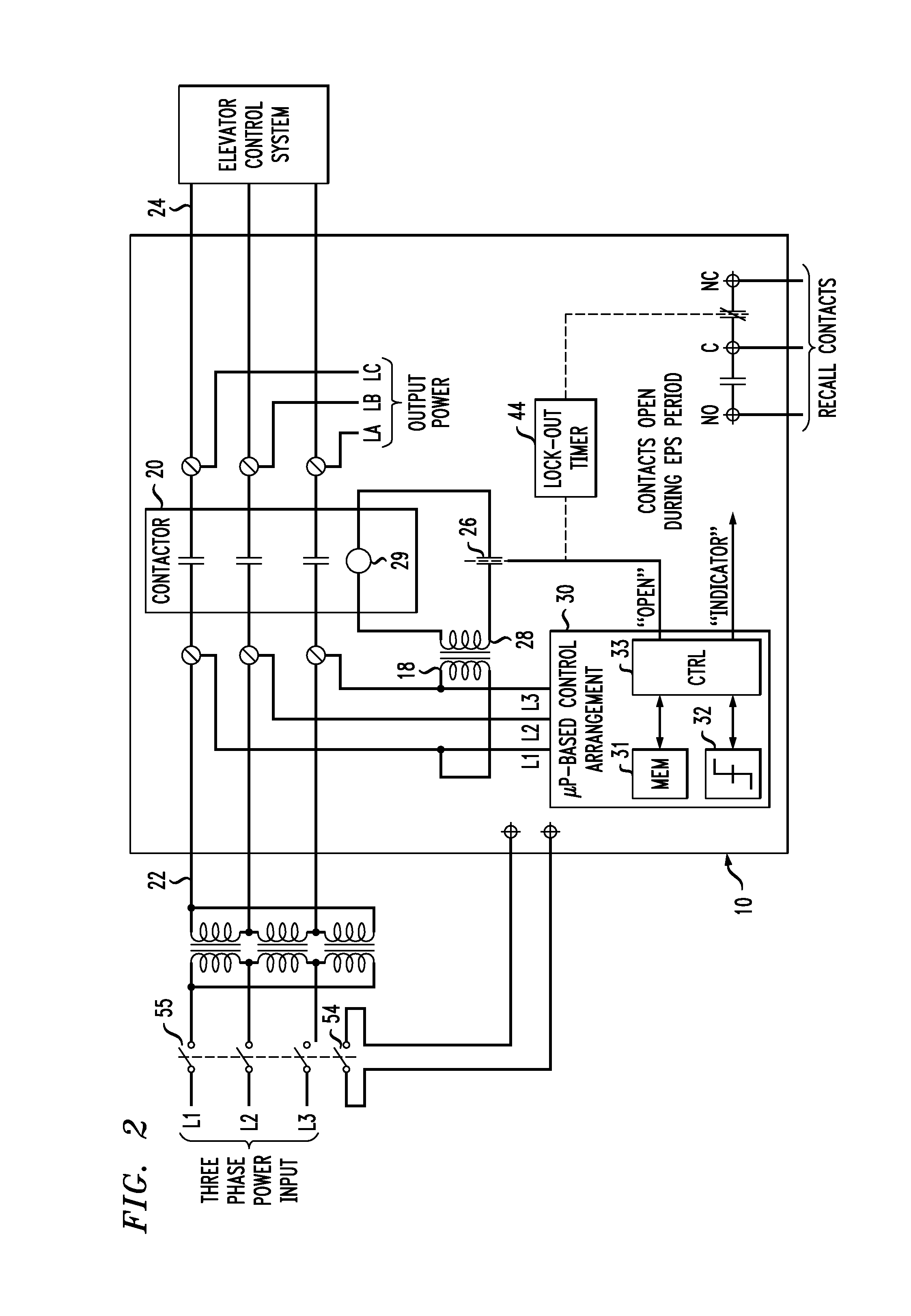
[0019]FIG. 1 is block diagram of an overall power system for a traction elevator and FIG. 2 is a more detailed circuit diagram of the relevant aspects of a back-up power system 10. The back-up power system 10 consists of three major areas: 1) normal power control; 2) microprocessor-based control arrangement for power sensing and inverter timing systems; and 3) a backup power generation system.

[0020]Referring to FIGS. 2 and 3, normal power control is done via the main contactor 20 and supporting systems. The normal power input source is connected on the line side 22 of the main contactor 20. The elevator system load (i.e., the traction motor itself) is connected on the load side 24 of the main contactor 20. Under normal power conditions, the power on the line side of the main contactor 20 is connected through a normally-closed contact 26 (and perhaps an optional step-down transformer 28) to the line side output of contactor 20. Normally-closed contact 26 is shown as one element of a ...


PUM


Abstract

An emergency power supply for a traction elevator system utilizes a microprocessor-based control arrangement with pulse-width modulator technology to create an efficient, cost-effective back-up power system for a traction elevator. The microprocessor-based control arrangement is used to sense a power loss, or any type of irregularity in the power supply. Upon sensing some type of power malfunction, the microprocessor-based control arrangement disconnects the elevator system from the main power source and then generates a control signal to initiate the supply of back-up power. Once the elevator electrical system has been recharged and stabilized, the microprocessor-based control arrangement will sense that recovery has occurred and will then provide an appropriate speed and direction command to the traction motor drive system.

Description

CROSS-REFERENCE TO RELATED APPLICATIONS[0001]This application claims the benefit of U.S. Provisional Application Ser. No. 61 / 757,943, filed Jan. 29, 2013 and herein incorporated by reference.TECHNICAL FIELD[0002]The present invention relates to power system controls for traction elevators and, more particularly, to a microprocessor-controlled emergency back-up power system for traction elevators.BACKGROUND OF THE INVENTION[0003]With the globalization of the elevator industry there has been a trend to standardize elevator systems worldwide. This trend is leaning toward the use of traction systems for smaller elevator applications (i.e., less floors). Previously, hydraulic elevator systems were commonly used in applications with less than seven landings. The trend anticipates that these applications will begin to utilize traction elevator systems. Such systems must be provided with emergency or back-up power systems that supply power not only to the controller, door operator, and valv...

Claims


Application Information

Patent Timeline
IPC IPC(8): B66B9/00H02J9/06
CPCH02J9/062B66B9/00B66B5/027Y02B50/00B66B11/04H02J9/061H02M5/458
Inventor HALL, JAMES C.
Owner REYNOLDS & REYNOLDS ELECTRONICS
Learn More