
Robot cleaner and control method thereof

a robot cleaner and cleaning tool technology, applied in the field of robot cleaners, can solve the problems of user inconvenience and foreign substances on the floor, and achieve the effects of reducing the manufacturing cost of the robot cleaner, and accurately measuring the amount of water absorbed

Active Publication Date: 2014-07-31
SAMSUNG ELECTRONICS CO LTD
View PDF19 Cites 37 Cited by
  • Summary
  • Abstract
  • Description
  • Claims
  • Application Information

AI Technical Summary

Benefits of technology

The patent describes a robot cleaner that can accurately measure the amount of water absorbed in its cleaning tool using capacitance sensors. This is done by designing the robot cleaner to prevent the influence of air temperature and humidity, and by automatically adding the appropriate amount of water to the cleaning tool based on the measured water level. This results in improved cleaning performance and user satisfaction.

Problems solved by technology

However, when a robot cleaner cleans a floor according to the dry-type cleaning method, some foreign substances may remain on a floor even after cleaning is completed since the robot cleaner cannot suck up foreign substances stuck on the floor or being larger than a specific size.
However, when a user cleans a floor using a robot cleaner for wet cleaning, the user must check an amount of water of a pad and add water to the pad if necessary, which causes the user's inconvenience.

Method used


Image

  • Robot cleaner and control method thereof
  • Robot cleaner and control method thereof
  • Robot cleaner and control method thereof

Examples


Embodiment Construction

[0037]Reference will now be made in detail to embodiments, examples of which are illustrated in the accompanying drawings, wherein like reference numerals refer to like elements throughout.

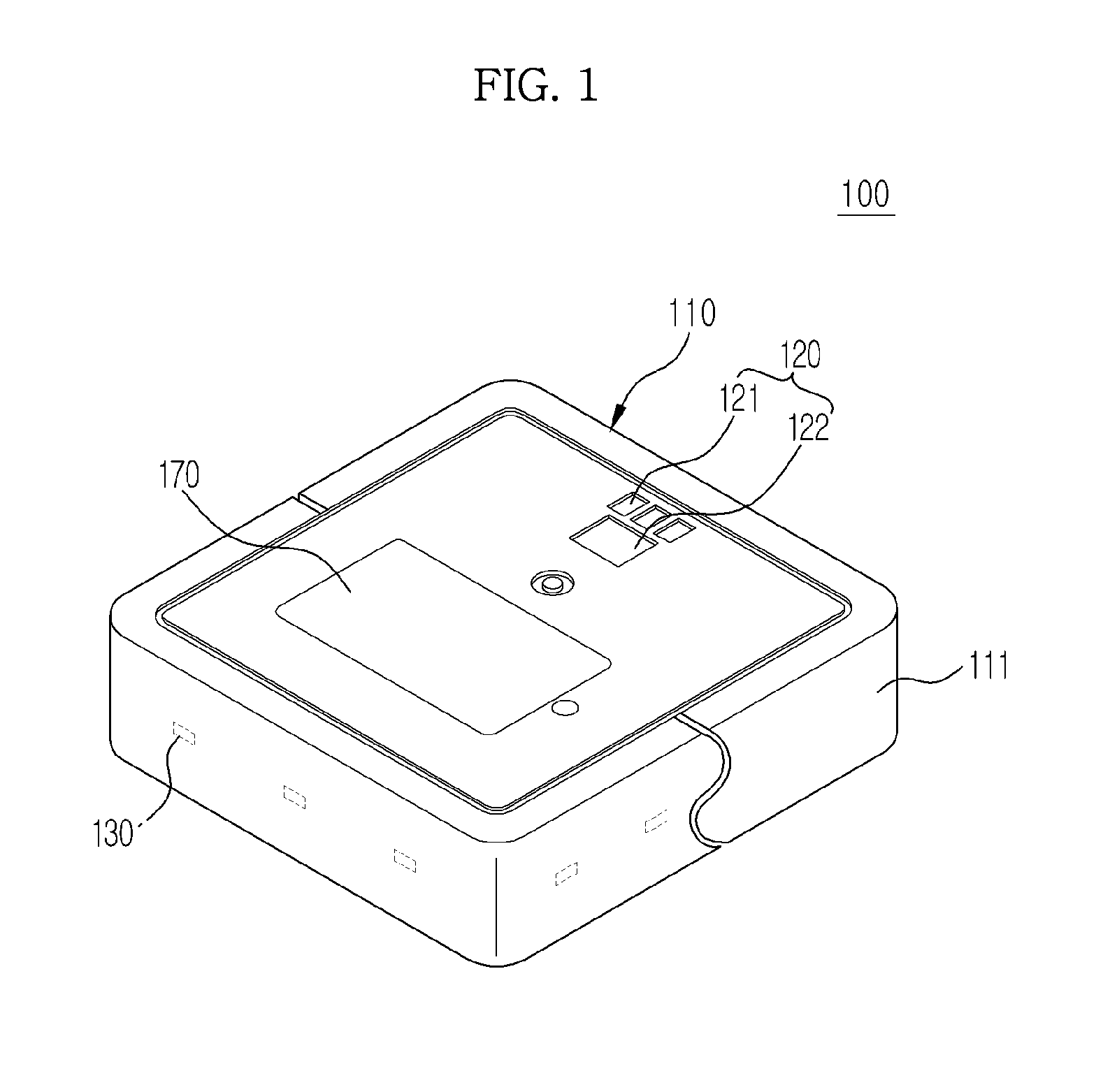
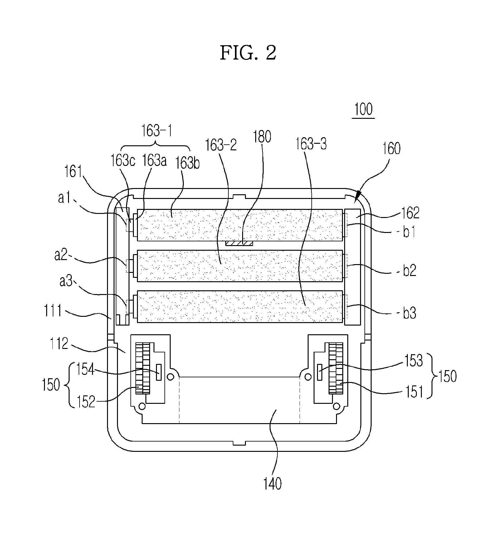
[0038]FIGS. 1 to 4 are views illustrating a robot cleaner 100 according to an exemplary embodiment.

[0039]FIG. 1 is a perspective view of the robot cleaner 100, FIG. 2 is a bottom view of the robot cleaner 100, FIG. 3A is a bottom view of the robot cleaner 100 when a cleaning tool assembly 160 has been separated from a main body 110, FIG. 3B is a cross-sectional view of the robot cleaner 100, cut along an x-x′ line, and FIG. 4 is an exploded perspective view of the cleaning tool assembly 160 of the robot cleaner 100.

[0040]Referring to FIG. 1, the robot cleaner 100 includes the main body 110 constructing an external appearance of the robot cleaner 100, a user interface 120 mounted on the upper part of the main body 110 to receive driving information, schedule information, etc. and display operation ...


PUM


Abstract

A robot cleaner may include a main body; a traveling assembly moving the main body; a cleaning tool assembly installed in the lower part of the main body, and contacting a floor to clean the floor; a water-feeding unit supplying water to the cleaning tool assembly; and a capacitance measurer contacting the cleaning tool assembly, and measuring capacitance of the cleaning tool assembly in order to calculate an amount of water of the cleaning tool assembly. Accordingly, by measuring an amount of water of a cleaning tool installed in a robot cleaner based on capacitance, it is possible to accurately measure an amount of water absorbed in a cleaning tool.

Description

CROSS-REFERENCE TO RELATED APPLICATIONS[0001]This application claims the priority benefit of Korean Patent Application No. 10-2013-0011520, filed on Jan. 31, 2013 in the Korean Intellectual Property Office, the disclosure of which is incorporated herein by reference.BACKGROUND[0002]1. Field[0003]Embodiments relate to a robot cleaner for improving efficiency of wet cleaning, and a control method thereof.[0004]2. Description of the Related Art[0005]In general, a robot cleaner automatically cleans an area to be cleaned by sucking up foreign substances such as dust from a floor while autonomously traveling about the cleaning area without user manipulation.[0006]The robot cleaner cleans a floor using a cleaning tool while autonomously traveling about a cleaning area. During cleaning, the robot cleaner senses obstacles or walls located in an area to be cleaned through various sensors, and controls a cleaning path or a cleaning operation based on the sensed results.[0007]Most of robot clea...

Claims


Application Information

Patent Timeline
Patent Type & Authority Applications(United States)
IPC IPC(8): A47L11/24
CPCA47L11/24A47L11/4002A47L11/4011A47L11/4041A47L11/4088A47L2201/00A47L9/28B25J9/16G01N27/22
Inventor JUNG, JAE YOUNGLEE, SAHNG JINJUNG, HYUN SOOKIM, DONG WONLEE, DONG HOON
Owner SAMSUNG ELECTRONICS CO LTD
Learn More