
Countercurrent oxygen enhanced torrefaction

a technology of countercurrent oxygen and torrefaction, which is applied in the direction of combustion types, drying machines, lighting and heating apparatuses, etc., can solve the problems of unfavorable addition of water, lower heating value of fuels based on renewable biomass, and lower energy density, so as to reduce heating and torrefaction time and energy efficiency.

Active Publication Date: 2014-07-31
BIOENDEV
View PDF6 Cites 17 Cited by
  • Summary
  • Abstract
  • Description
  • Claims
  • Application Information

AI Technical Summary

Benefits of technology

This patent text discusses the use of torrefied biomass as a fuel in existing power plants designed for fossil fuels. The technical effects of the patent text include improving the heating value of torrefied biomass, decreasing the energy needed for grinding the material into a fine powder, and increasing the energy yield and mass yield while decreasing the heating and torrefaction time. These improvements can lead to more efficient and cost-effective use of torrefied biomass as a fuel in existing power plants.

Problems solved by technology

Compared to fossil fuels such as coal, oil and natural gas, fuels based on renewable biomass have been described to suffer from lower heating value, lower energy density and therefore higher transportation costs.
However milling of the torrefied biomass is an energy demanding process and thus it is important to keep the energy needed for milling of the torrefied material in to a powder as low as possible.
However, if the heating value of the torrefied material is low, addition of water can be unfeasible since the low energy value of the produced slurry can prevent efficient burning of the slurry in the boiler.
Besides from facilitating the use of a water based slurry as fuel in a pressurized system, a material with high heating value followed by densification with increased energy density also decreases transportation and storage costs.

Method used


Image

  • Countercurrent oxygen enhanced torrefaction
  • Countercurrent oxygen enhanced torrefaction
  • Countercurrent oxygen enhanced torrefaction

Examples


example 1

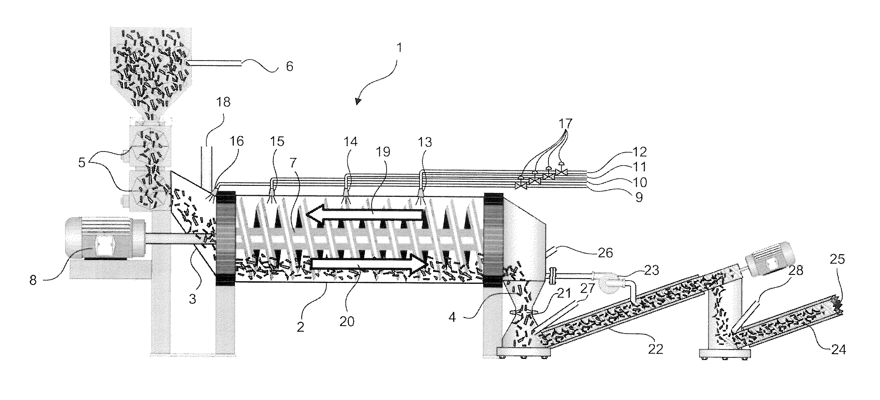
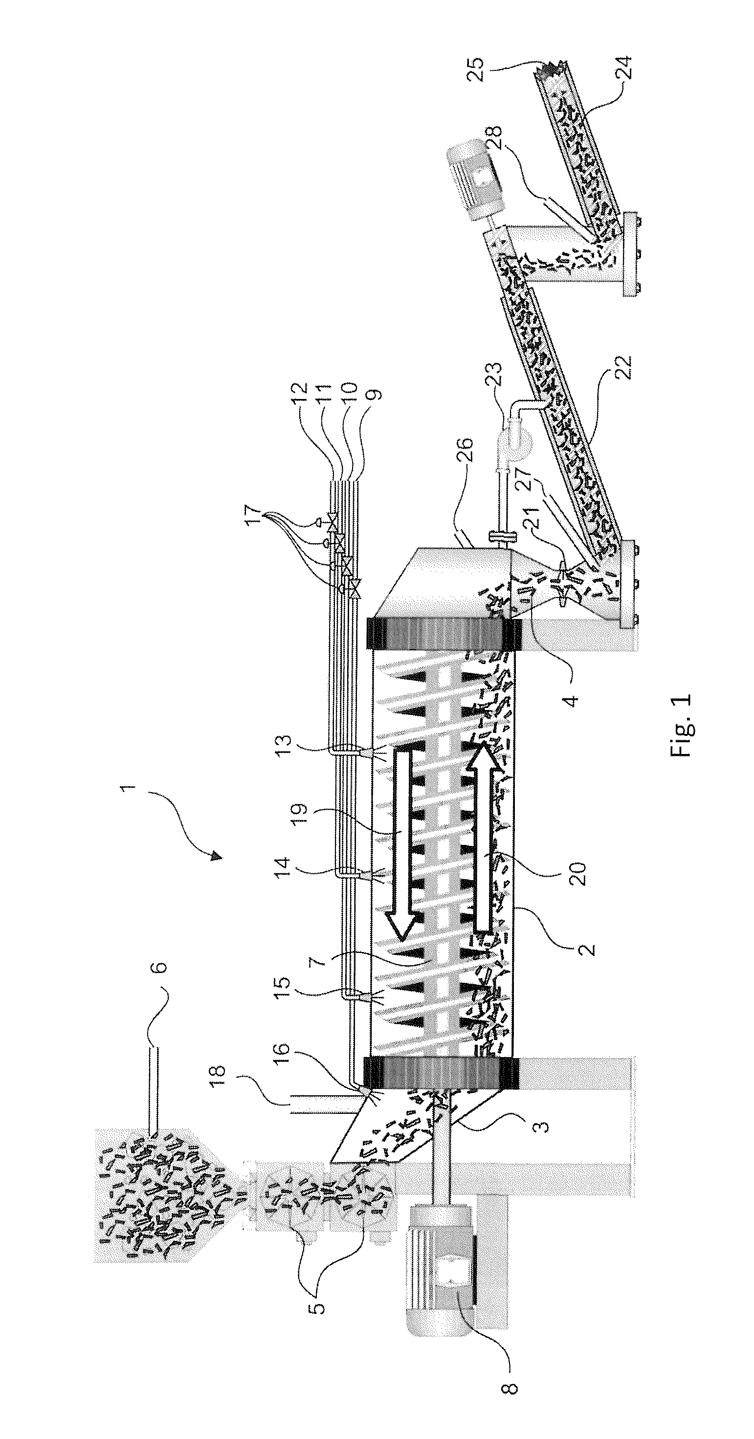
[0070]FIG. 1 shows a system for the torrefaction of a biomass (1) comprising a torrefaction reactor (2) having a biomass inlet (3) and a biomass outlet (4). The biomass is predried to a moisture content of about 5% (w / w) prior to feeding the biomass in to the torrefaction reactor (2) via rotary vane feeders (5). The moisture content in the biomass is controlled by a moisture probe (6). When the biomass enters the torrefaction reactor (2) via the biomass inlet (3) the temperature of the biomass is about 100° C. The biomass is transported through the torrefaction reactor (2) by means of a transport screw (7) which comprises helicoidal material transport device fixed to a central shaft (7). The speed of the biomass transport is regulated by the rotational speed of the transport screw (7) which is driven by a transport screw engine (8). An oxygen containing gas is injected to the torrefaction reaction via a gas inlet for injection of an oxygen containing gas (9, 10, 11, 12). The oxygen ...

example 2

[0071]Torrefaction of biomass was performed in a continuous torrefaction pilot plant having a torrefaction reactor comprising a 1.7 m long rotating drum with an internal screw fixed to the drum. A heated transport screw before the torrefaction reactor acted as a preheater and heated the bone-dry biomass to about 150° C.

[0072]In the torrefaction reference experiments, external electrical heaters heated the reactor. The heaters were controlled so that an isothermal drum surface temperature was reached and so that the biomass was heated to the final torrefaction temperature read at the exit of the torrefaction reactor through an IR-thermometer. The torrefaction gases were flowing concurrently with the biomass and withdrawn from the torrefaction reactor at the end of the reactor.

[0073]In the “counter current oxygen enhanced torrefaction experiments” (CC-OET) all external electrical drum heaters were turned off except for the electrically heated preheater. Oxygen containing gas was injec...

example 3

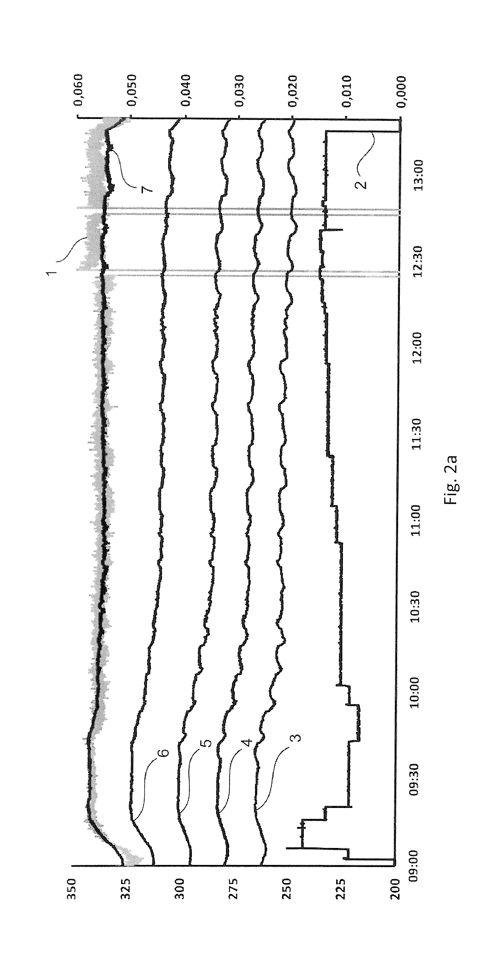
[0080]FIG. 2a shows that the temperature of the biomass can be kept stable using the method according to the present invention. In this experiment a wood mixture was torrefied at a biomass surface temperature of about 338° C. with countercurrent gas flow during injection of air and 7.5 minutes residence time. At time 12:00 the process was determined to be at steady-state. The x-axis shows the time in hours:minutes, the left y-axis shows the temperature and the right y-axis shows the lambda value. Curve (1) shows the biomass surface exit temperature, curve (2) shows the corresponding lambda value, curve (3-7) shows the gas temperatures in the centre of the torrefaction drum, where (3) is closest to the biomass inlet and (7) is closest to the biomass exit.

[0081]FIG. 2b shows the combustibility of the torrefaction generated gas during torrefaction of the wood mixture at 338° C. biomass surface temperature with countercurrent gas flow during injection of air and 7.5 minutes residence ti...


PUM

PropertyMeasurementUnit
temperatureaaaaaaaaaa

Abstract

The invention relates to a method of torrefaction of an optionally predried biomass in a torrefaction reactor such that torrefied biomass and torrefaction gases are obtained, and wherein an oxygen-containing gas is supplied to the torrefaction reactor at a first position in the reactor such that oxygen reacts with components of the torrefaction gases under the formation of heat and wherein torrefaction gases are withdrawn from the torrefaction reactor at a second position of the torrefaction reactor and wherein the first position is located downstream of the second position in relation to a biomass transport direction in the torrefaction reactor such that the torrefaction gases moves through the torrefaction reactor countercurrent with the biomass transport and wherein the optionally predried biomass has a temperature of between 30° C. and 230° C., preferably between 50° C. and 200° C., most preferably between 60° C. and 180° C. when entering the torrefaction rector.

Description

TECHNICAL FIELD[0001]The present invention relates to the field of torrefaction of biomass. In particular it relates to a torrefaction process which increases the energy yield in the torrefaction process, increases the energy density of the torrefied material and reduces the energy needed for grinding the torrefied material into a fine powder.BACKGROUND[0002]To be able to compete with and replace fossil fuel energy carriers such as coal, oil and natural gas, lignocellulosic biomass would benefit from some form of pre-treatment method to overcome inherent drawbacks. The pre-treatment method torrefaction has been shown to improve biomass fuel qualities such as heating value, energy density, water content, milling characteristics, feeding and hydrophobic properties [1-4]. These improvements establish torrefaction as a key process in facilitating an expanding market for biomass raw materials. Torrefaction is a thermal pre-treatment method that normally takes place in a substantially ine...

Claims


Application Information

Patent Timeline
Patent Type & Authority Applications(United States)
IPC IPC(8): C10L5/44F23G5/033
CPCF23G5/033C10L5/447C10L5/366C10L9/083F26B17/20F26B23/022F26B2200/02Y02E50/10C10L5/44C10L9/08F26B9/08Y02E50/30
Inventor OLOFSSON, INGEMARNORDWAEGER, MARTINSANDSTROM, ERIKPOMMER, LINDANORDIN, ANDERS
Owner BIOENDEV
Learn More