
Fuel Cell System

a fuel cell and system technology, applied in the field can solve the problems of frequent adverse external conditions of fuel cell systems, inability to prevent, and inability to use fuel cells

Inactive Publication Date: 2014-07-24
DAIMLER AG
View PDF3 Cites 0 Cited by
  • Summary
  • Abstract
  • Description
  • Claims
  • Application Information

AI Technical Summary

Benefits of technology

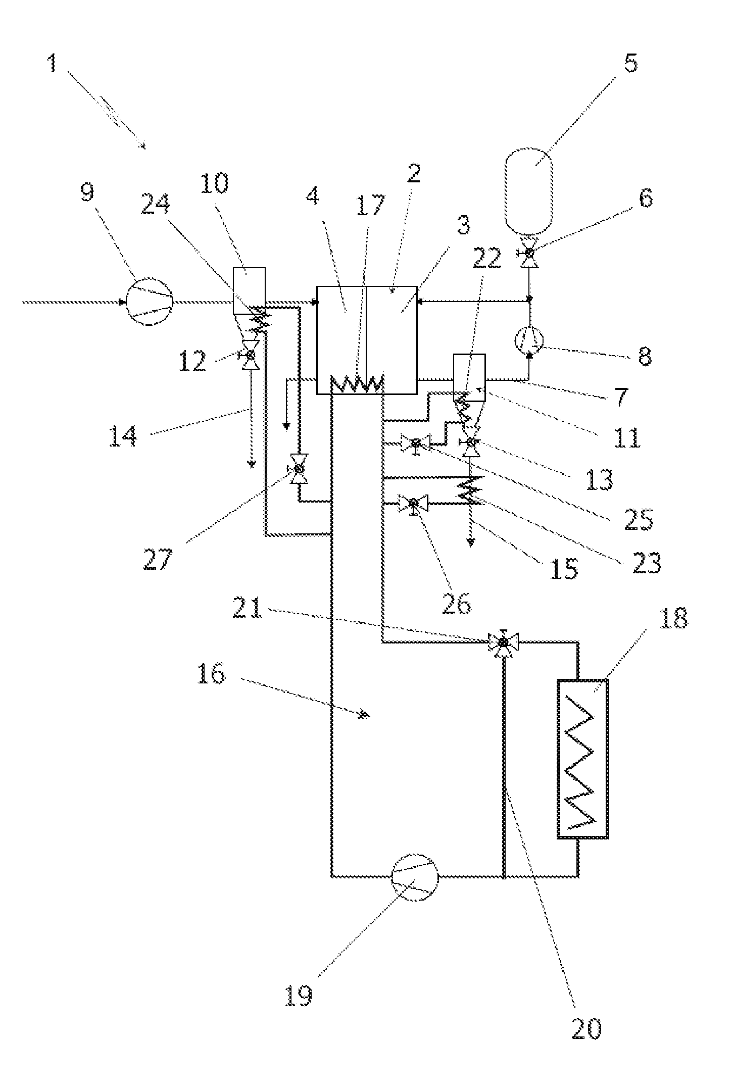
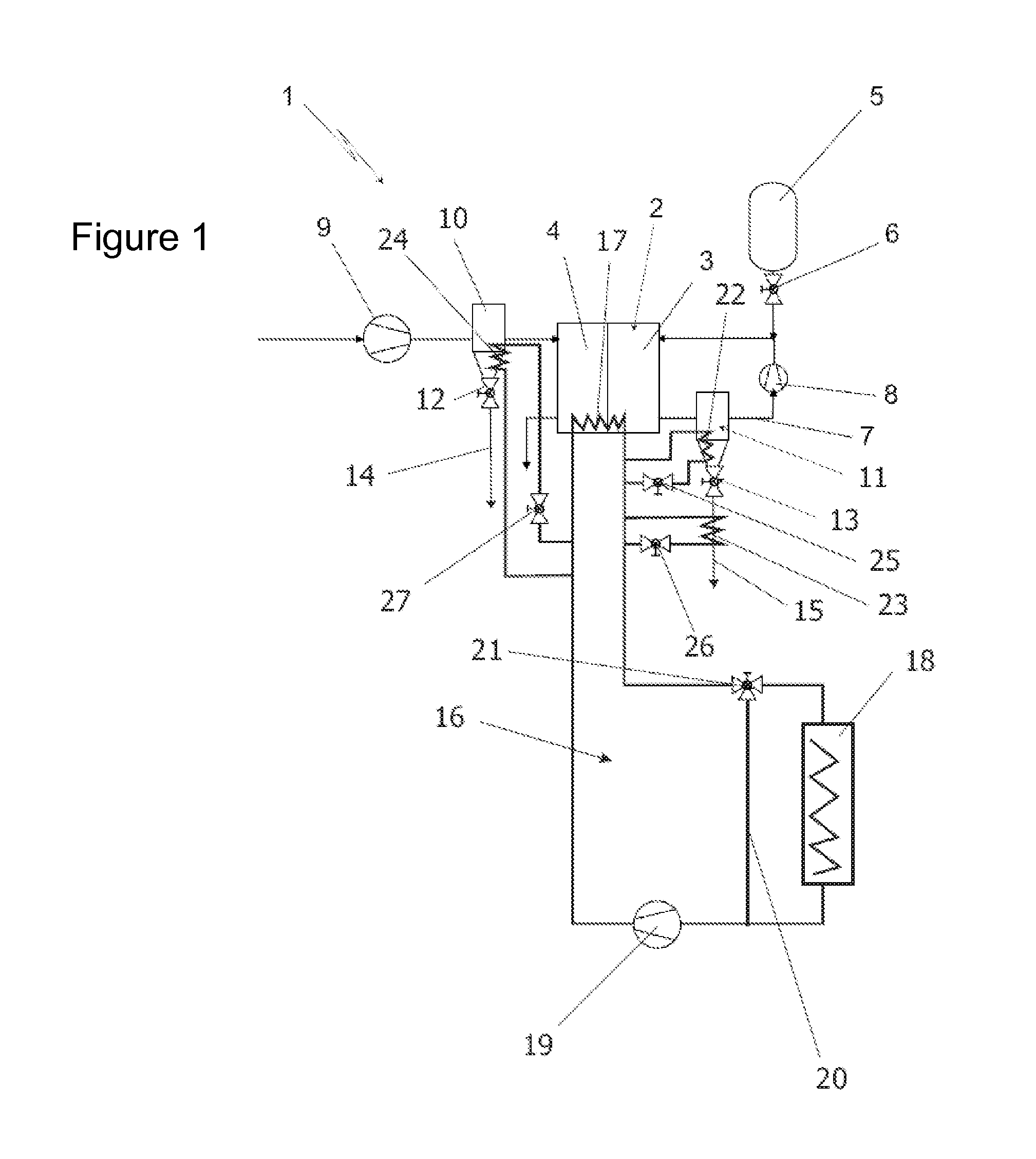
The fuel cell system described in this patent is designed to start quickly and efficiently in adverse environmental conditions, such as low temperatures. It uses heat exchangers with cooling water to thaw the water-conducting parts and components quickly. The system has a high-temperature cooling circuit and a low-temperature cooling circuit, which allows for efficient thawing of the water-conducting parts and components. The cooling circuit can be switched to circulate only in the fuel cell and the water-conducting parts and components, ensuring rapid and reliable thawing of the system. This design requires less energy to start the system and makes it suitable for use in vehicles exposed to adverse environmental conditions.

Problems solved by technology

It is also known that the use of fuel cell systems, in particular in vehicles, also frequently occurs under adverse external conditions.
Therefore, this water freezes very quickly at temperatures below the freezing point, which cannot be prevented even with additives or the like, since the water does not form from the supplied starting materials until the fuel cell is in operation.
Since the liquid water cannot be completely flushed from all water-conducting parts and components when the fuel cell system is switched off, it is often necessary to thaw water-conducting components in the fuel cell when the fuel cell system is started at temperatures below the freezing point.
However, these electric heating elements require a comparatively large quantity of electrical energy when the fuel cell system is started.
If this is a fuel cell system that is used, for example, in a vehicle as a mobile fuel cell system, energy is typically not available or is available only to a very limited extent, since the vehicle, like a conventional vehicle, often has only a starter battery for starting the system.
The energy necessary for thawing the water-conducting parts and components thus places a significant load on the system during the start phase, and requires high-capacity electrical energy store units as an absolute necessity, thus making the design correspondingly heavy, large, and costly.

Method used


Image

  • Fuel Cell System
  • Fuel Cell System

Examples


Embodiment Construction

[0015]The sole figure illustrates a fuel cell system 1 according to the invention. The fuel cell system includes a fuel cell 2 having an anode region 3 and a cathode region 4. The anode region 3 of the fuel cell 2 is supplied with hydrogen from a compressed gas store 5 via a throttle valve 6. The unconsumed exhaust gas from the region of the anode chamber 3 passes via a recirculation line 7 and a recirculation conveying unit 8 back into the region of the anode chamber 3, which is resupplied with this hydrogen together with fresh hydrogen from the compressed gas store 5. This design is also generally known as an anode loop, and for the exemplary embodiment illustrated here is understood to be strictly an example. In principle, it would also be conceivable to provide the fuel cell 2 without an anode loop, for example as a dead-end fuel cell, or with discharge of the unconsumed exhaust gas to a catalytic burner or the like, for example.

[0016]The cathode chamber 4 of the fuel cell 2 is ...


PUM

PropertyMeasurementUnit
temperatureaaaaaaaaaa
electrical propulsion energyaaaaaaaaaa
temperaturesaaaaaaaaaa

Abstract

A fuel cell system includes at least one fuel cell, water-conducting parts and components in the region of the supply and discharge of starting materials and products to and from the fuel cell, and at least one cooling circuit containing liquid cooling medium for cooling the fuel cell. The water-conducting parts and components are in thermal contact with the cooling medium, at least during individual operating phases of the fuel cell.

Description

BACKGROUND OF THE INVENTION[0001]Exemplary embodiments of the invention relate to a fuel cell system having at least one fuel cell and to the use of a fuel cell system.[0002]Fuel cell systems are known from the general prior art. Fuel cell systems frequently have fuel cells designed in the form of so-called PEM fuel cells. Such fuel cell systems are preferably used in mobile applications, such as in motor vehicles, for at least partially generating the electrical propulsion energy. In these types of fuel cell systems it is customary for various system components, for example an air supply subsystem, a fuel supply subsystem, and the like to be present. Since, in principle, product water occurs in the region of the fuel cell and must be discharged, fuel cell systems of this type generally have at least one, but typically multiple, water separator(s) for separating liquid water, present in the form of droplets, from gas flows from and / or to the fuel cell. These water separators are gen...

Claims


Application Information

Patent Timeline
Patent Type & Authority Applications(United States)
IPC IPC(8): H01M8/04
CPCH01M8/04007H01M8/04029H01M8/04067H01M8/04164H01M8/04253Y02E60/50
Inventor BAUR, THOMASMAZZOTTA, COSIMOSCHABEL, HANS-JOERG
Owner DAIMLER AG
Learn More