
Image processing apparatus, microscope system, and recording medium

a technology of image processing and microscope, applied in the field of image processing apparatus, microscope system, and recording medium, can solve problems such as image quality reduction and image generation

Active Publication Date: 2014-07-17
EVIDENT CORP
View PDF0 Cites 13 Cited by
  • Summary
  • Abstract
  • Description
  • Claims
  • Application Information

AI Technical Summary

Benefits of technology

The present invention provides an image processing apparatus that can generate multiple normalized images by correcting the brightness of different images based on different imaging conditions. The apparatus can then combine these normalized images to create a combined image with gradation values close to those of the brightest image. This results in a more accurate and detailed image. The invention also includes a microscope system with this image processing apparatus and a non-transitory program for computer execution. The technical effects of this invention are improved accuracy and detail in image processing and analysis.

Problems solved by technology

Therefore, although the blown out highlights and the blocked up shadows are prevented, an image with reduced image quality is generated.

Method used


Image

  • Image processing apparatus, microscope system, and recording medium
  • Image processing apparatus, microscope system, and recording medium
  • Image processing apparatus, microscope system, and recording medium

Examples


first embodiment

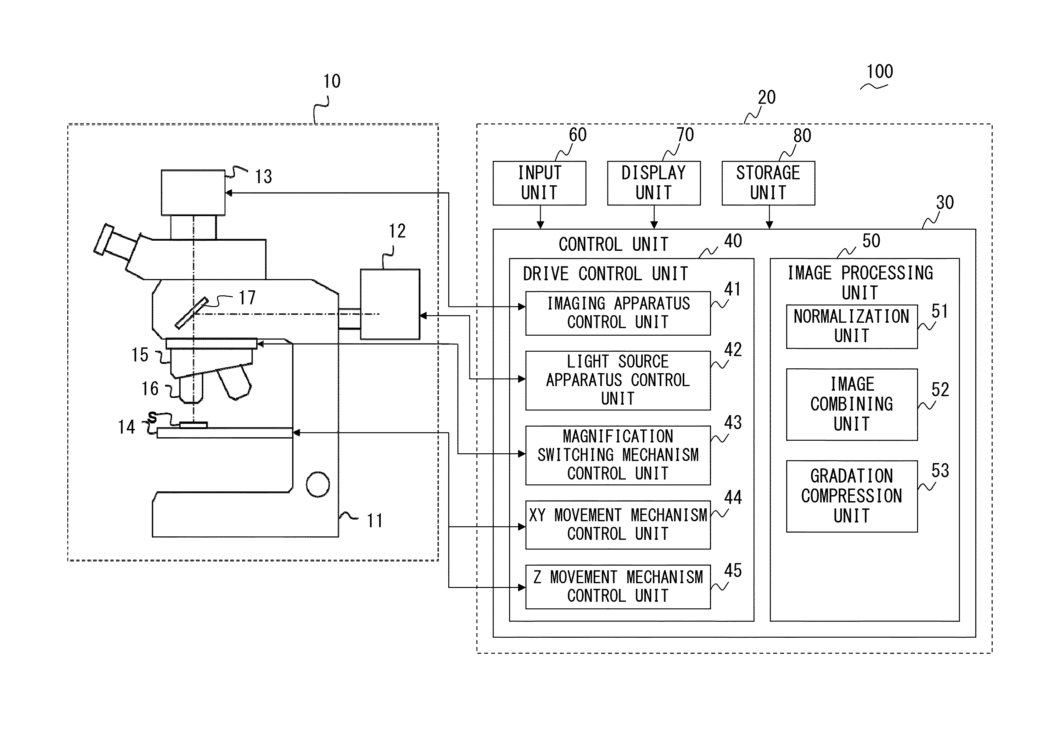
[0086]FIG. 9 is a flow chart of a weighting combining process according to the present embodiment executed by the host system 20 included in the microscope system 100 illustrated in FIG. 4. In the weighting combining process according to the present embodiment illustrated in FIG. 9, when the gradation lv2 of pixel of the non-reference normalized image is smaller than a threshold Thlv2 calculated based on the gradation lv1 of pixel of the reference normalized image, the image combining unit 52 calculates the gradation lvOut of pixel of the HDR image by multiplying the gradation lv1 and the threshold Thlv2 by the combining ratio (ratio of the weights wt1 and wt2) determined by the gradation lv1.

[0087]The imaging combining unit 52 calculates the weight wt1 of pixel of the reference normalized image and the weight wt2 of pixel of the non-reference normalized image based on the weight characteristics WC1 and WC2 calculated in step S35 of FIG. 6 and based on the gradation of pixel of the ...

second embodiment

[0102]FIG. 13 is a flow chart of a weighting combining process according to the present embodiment executed by the host system 20 included in the microscope system 100 illustrated in FIG. 4. The threshold process is applied to the gradation of pixels (for example, gradation lv2 and gradation lvOut) in the weighting combining process of the first embodiment, whereas the weighting combining process according to the present embodiment is different in that the weight is adjusted. More specifically, as illustrated in FIG. 13, the weighting combining process according to the present embodiment is designed to combine the images by reducing the weight wt2 of the non-reference normalized image smaller than the weight determined by the initial combining ratio if the gradation lvOut of pixel of the HDR image calculated based on the combining ratio (ratio of the weights wt1 and wt2) determined by the gradation lv1 of pixel of the reference normalized image is smaller than the gradation lv1 of p...


PUM


Abstract

An image processing apparatus includes: a normalization unit that generates a plurality of normalized images by correcting, based on different imaging conditions, brightness of a plurality of images at different brightness obtained by imaging a same subject with the different imaging conditions; and an image combining unit that generates a combined image by combining the plurality of normalized images. When the normalized image corresponding to a reference image that is a brightest image among the plurality of images is defined as a reference normalized image, the image combining unit combines the reference normalized image and a non-reference normalized image that is the normalized image other than the reference normalized image to bring gradation of pixel of the combined image close to gradation of pixel of the reference normalized image if the gradation of pixel of the combined image is smaller than the gradation of pixel of the reference normalized image.

Description

CROSS REFERENCE TO RELATED APPLICATIONS[0001]This application is based upon and claims the benefit of priority from prior Japanese Patent Application No. 2013-004006, filed Jan. 11, 2013, the entire contents of which are incorporated herein by this reference.BACKGROUND OF THE INVENTION[0002]1. Field of the Invention[0003]The present invention relates to an image processing apparatus, a microscope system, and a recording medium for combining a plurality of images to generate an image with a higher dynamic range.[0004]2. Description of the Related Art[0005]Conventionally, a high dynamic range process (hereinafter, “HDR process”) is known in the field of an image processing apparatus provided with an imaging apparatus such as a microscope system, wherein a plurality of images (hereinafter, “original images”) taken with different exposure conditions are combined to generate an image (hereinafter, “HDR image”) with a higher dynamic range than that of the original images.[0006]According t...

Claims


Application Information

Patent Timeline
IPC IPC(8): G02B21/36G06T11/60G06T5/00
CPCG02B21/367G06T5/007G06T11/60G06T5/40G06T5/50G06T2207/10016G06T2207/10056G06T2207/10152G06T2207/20208G06T2207/20221G06T2207/30141G06T5/92
Inventor KAMINAGA, SHIGETO
Owner EVIDENT CORP
Learn More