
Mobility State Aware Mobile Relay Operation

a mobile relay and mobile state technology, applied in the field of radio communication, can solve the problems of significant signaling overhead, long service life, and high throughput, and achieve the effect of reducing the probability of ping-pong handover

Active Publication Date: 2014-07-10
TELEFON AB LM ERICSSON (PUBL)
View PDF15 Cites 102 Cited by
  • Summary
  • Abstract
  • Description
  • Claims
  • Application Information

AI Technical Summary

Benefits of technology

This patent is about a system that helps control a device's movement and measurements, as well as selecting and reselecting cells. It also reduces the likelihood of "ping-pong" handovers, which can improve the device's overall performance and reliability.

Problems solved by technology

Relay Nodes, RNs, can extend the coverage of cellular networks, enhance capacity in hotspots, increase effective cell throughput, and reduce average radio-transmission power at the User Equipment, UE, especially in highly shadowed areas, thereby leading to longer UE battery life.
There are problems with providing high speed “group mobility,” where group mobility includes multiple and often many UEs traveling at high speed together, for example in trains and buses.
One problem is providing high throughput.
A third problem related to group HO is significant signaling overhead over the air interface.
A fourth problem is that the possibility of handover failures increases as many simultaneous or almost simultaneous HO requests are made to a given neighboring cell.
The introduction of RNs has its own set of challenges such as different vendors and different management entities.
Another RN challenge pertains to automatic neighbor cell relations involving RNs, and in particular, the limited numbers of PCIs.
Limiting the number of PCIs makes an initial PCI detection by the UE during cell search easier, but the limited number of PCIs inevitably leads to the reuse of the same PCI values in different cells.
The use of identical PCI by two cells in close proximity results in interference conditions that might hinder the identification and use of any of them.
Otherwise, if both cells have a common neighbor, handover measurements that are based on PCI become ambiguous and lead to confusing measurement reports or even to the handing over of a UE to the wrong cell, which can cause Radio Link Failure, RLF.
Therefore, a PCI which causes either collision or confusion is undesirable.
However, prediction errors caused by imperfections in map and building data and due to inaccuracies in propagation models have forced operators to resort to drive / walk tests to ensure proper knowledge of the coverage region and identify all relevant neighbors and handover regions.
Even the accuracy of drive / walk tests is questionable as some factors such as seasonal changes, e.g., the falling of leaves or snow melting, can alter the propagation conditions.
Also, the inaccuracy of cell coverage and neighbor relation assessment increases with time as the live network and its surroundings evolve over time.

Method used


Image

  • Mobility State Aware Mobile Relay Operation
  • Mobility State Aware Mobile Relay Operation
  • Mobility State Aware Mobile Relay Operation

Examples


example mechanisms

[0076 to identify the different mobility states are now described, followed by non-limiting example embodiments describing desired operation / behavior during each state and how to achieve them.

[0077]In order to align the mobile relay's operation / behavior with its mobility state, the mobile relay's mobility state has to be identified either by the mobile relay itself or another network node. This may be done using one or more of the following example mechanisms: positioning methods, non-positioning methods, and combined methods that use some elements of a positioning method and some elements of a non-positioning method.

[0078]In one non-limiting example embodiment, a mobile relay node is equipped with a suitable positioning system, which is used to determine its mobility state. The positioning method used for the mobility state determination can be satellite-based, e.g. GNSS, or non-satellite based or even a hybrid method, which uses elements of two or more positioning methods for posi...


PUM


Abstract

A mobility state of a mobile relay node is determined as one of three or more different mobility states. The mobile relay node may determine the mobility state itself or based on received information from another network node. Control information is determined based on the determined mobility state of the mobile relay node and an action is then performed or initiated based on the determined control information. The tree different mobility states may include moving, standing, and at least one additional mobility state. Example additional mobility states of the mobile radio node include: departing, arriving, or temporarily stopped.

Description

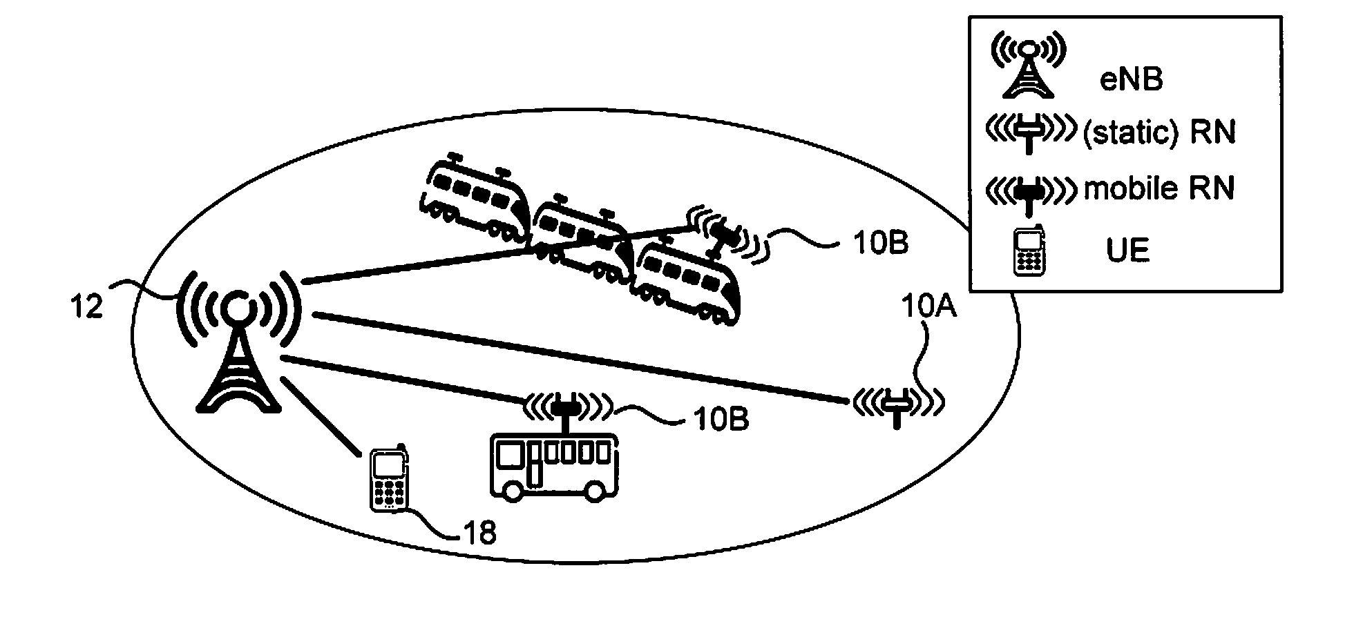
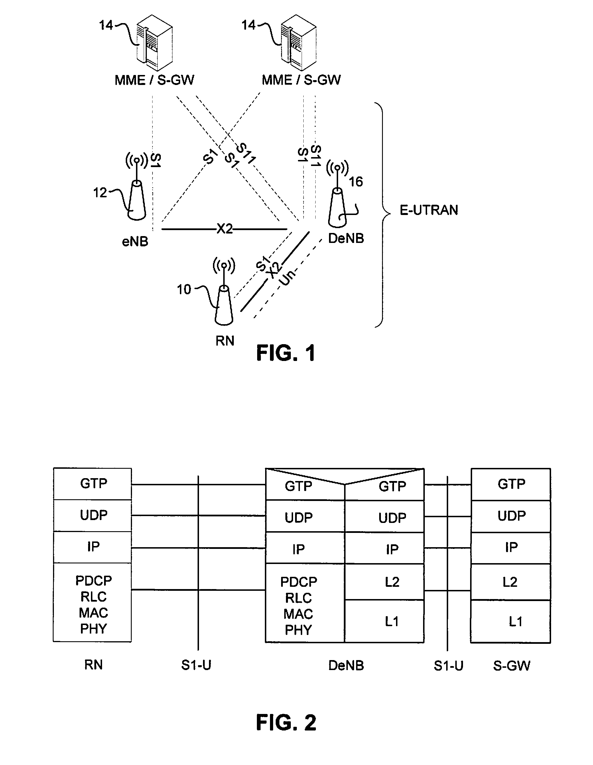
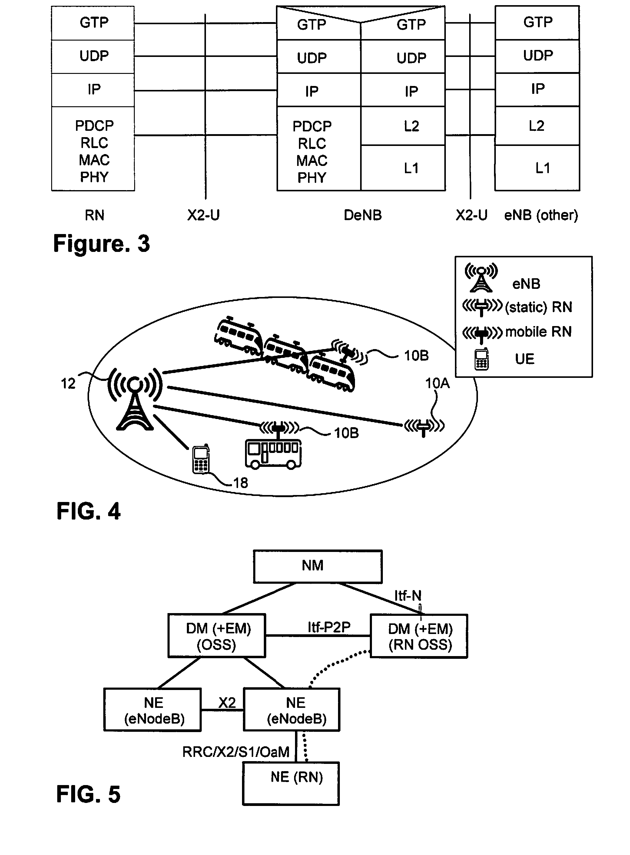
TECHNICAL FIELD[0001]The technology relates to radio communications, and in particular, to wireless networks that use relay nodes.INTRODUCTION[0002]Relay Nodes, RNs, can extend the coverage of cellular networks, enhance capacity in hotspots, increase effective cell throughput, and reduce average radio-transmission power at the User Equipment, UE, especially in highly shadowed areas, thereby leading to longer UE battery life. Because of these advantages, Long-Term Evolution, LTE,-Advanced corresponding to release 10 of LTE, the standardization of which is currently being finalized in the 3rd Generation Partnership Project, 3GPP, introduced support for RNs. An RN coverage cell, as specified in Release-10, Rel-10, appears to a UE as a separate cell distinct from a donor cell of a donor base station that connects the RN to a core network. An RN cell has its own Physical Cell ID, PCI, as defined in LTE Rel-8 and transmits its own synchronization channel, reference symbols, etc. The UE re...

Claims


Application Information

Patent Timeline
Patent Type & Authority Applications(United States)
IPC IPC(8): H04W36/34
CPCH04W36/34H04W36/14H04W48/18H04W84/005H04W36/324H04W36/322
Inventor TEYEB, OUMERKAZMI, MUHAMMEDMILDH, GUNNAR
Owner TELEFON AB LM ERICSSON (PUBL)
Learn More