Rapid adjustable wrench
a wrench and adjustable technology, applied in the field of quick adjustment wrenches, can solve the problems of low work efficiency and inconvenient us
- Summary
- Abstract
- Description
- Claims
- Application Information
AI Technical Summary
Benefits of technology
Problems solved by technology
Method used
Image
Examples
embodiment 1
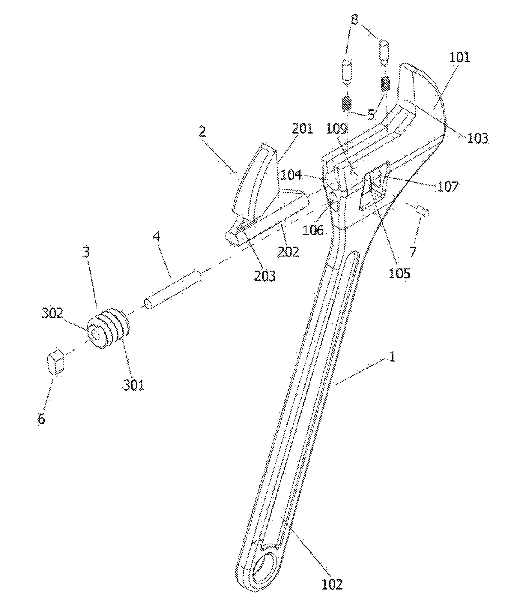
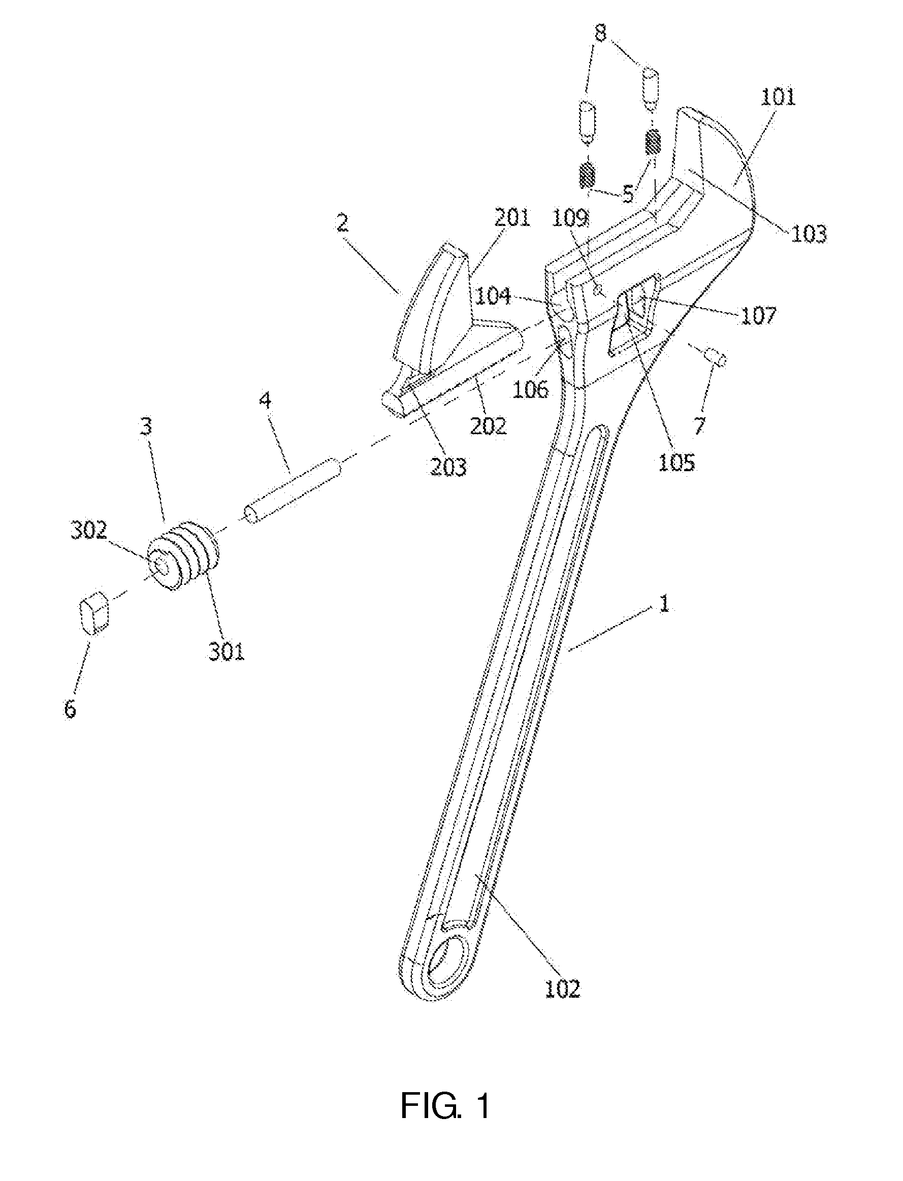
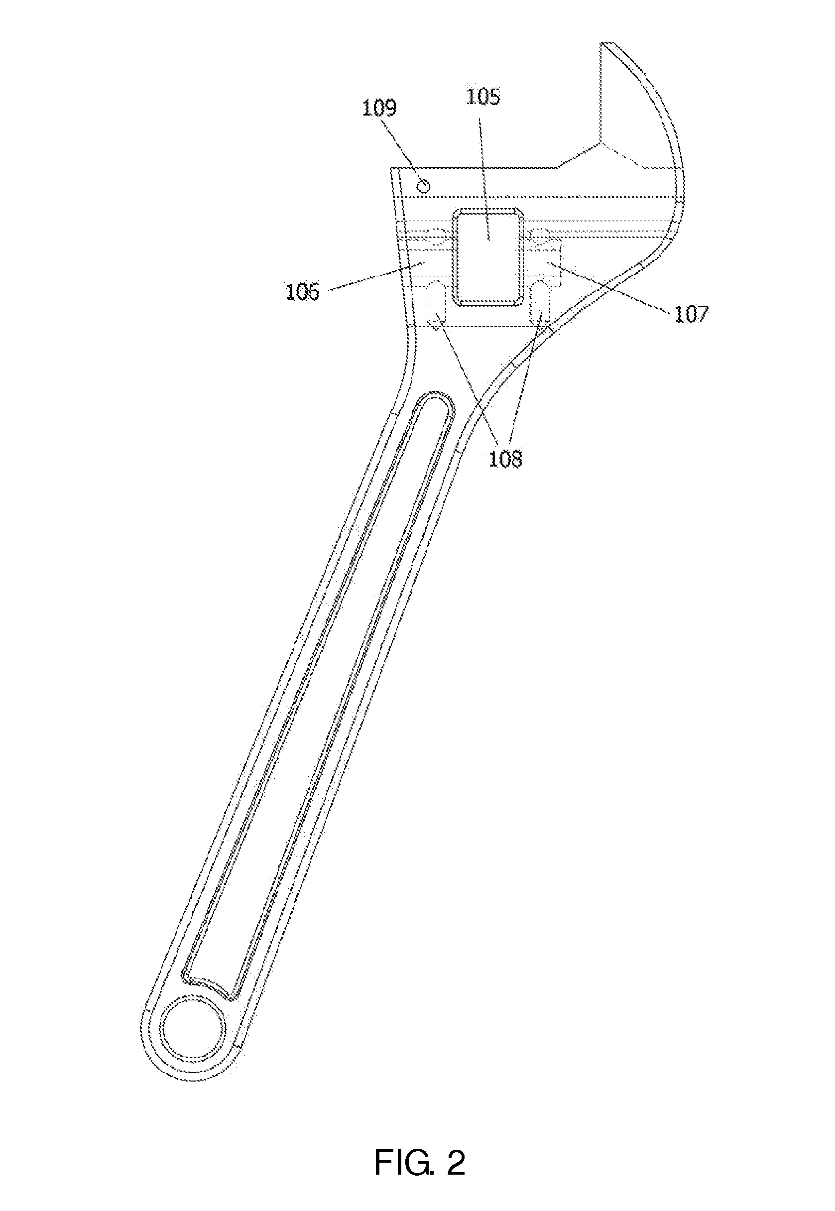
[0024]A adjustable wrench embodiment, referring to FIGS. 1 to 7, as shown in FIG. 1, the wrench is comprised of wrench body 1, adjustable wrench head 2, worm 3, pin shaft 4, spring 5, bond type wedge 6, stop pin 7, support pin 8, the front end of the wrench body 1 is a fixed wrench head 101, the back end of the wrench body is a handle 102, there is a workpiece clamping face 103 on the fixed wrench body, there is a workpiece clamping face 201 on the adjustable wrench head 2, as shown in FIG. 1, FIG. 2, FIG. 3, FIG. 4, 104 is the recess of the fixed wrench head, 105 is the rectangular through hole, 106 is the bond type through hole, 107 is the bond type blind hole, 108 is the spring hole, 109 is the stop hole, as shown in FIG. 1, FIG. 6, FIG. 7, inserting one end of the spring 5 into the spring hole 108 respectively, placing the worm 3 in the middle of the rectangular through hole 105, inserting the pin shaft 4 into the bond type through hole 106 from the outside of the wrench body, w...
embodiment 2
[0025]This embodiment is an improvement on the basis of the embodiment 1, please refer to the content disclosed in embodiment 1 to understood the parts similar to the embodiment 1 in this embodiment.
[0026]Referring to FIG. 8 and FIG. 9, a rapid adjustable wrench, includes a fixed wrench head 101 integrated with the handle 102 of the wrench 1, and a adjustable wrench head 2 driven by the rotation of the worm 3, the teeth 202 are set on the adjustable wrench head, which can mesh with the spiral teeth of the worm, the wrench is set with a through window 105 (rectangular through hole in embodiment 1) on the underside of the fixed wrench head, the support holes 106 and 107 are set on the side wall of the two horizontal sides of the through window, the pin shaft 4 which set in the support hole supports the worm in the through window; wherein, the aperture of the support hole in both sides of the through window is a elongated aperture (the bond type hole in embodiment 1) that enable the pi...
embodiment 3
[0028]This embodiment is an improvement on the basis of the embodiment 2, please refer to the content disclosed in embodiment 2 to understood the parts similar to the embodiment 2 in this embodiment, the content disclosed in embodiment 2 should also be as the content of the present embodiment, the repetitive description is not made herein.
[0029]In embodiments, the depressed length of the spring is to ensure that the length of the radial displacement of the worm teeth is one-half to four-fifths of the height of the highest teeth of the adjustable wrench head.
[0030]In order to increase the reliability, in this embodiment, the adjustable wrench head teeth have three teeth on the top end of the clamping face, which height is higher than that of the subsequent other teeth, the height of the other teeth is the same, the height of the other teeth is four-fifths of the height of three teeth on the top end. The method is to leave the three teeth of the adjustable wrench head teeth not moving...
PUM
 Abstract
Description
Claims
Application Information
 - R&D
- Intellectual Property
- Life Sciences
- Materials
- Tech Scout
- Unparalleled Data Quality
- Higher Quality Content
- 60% Fewer Hallucinations
Browse by: Latest US Patents, China's latest patents, Technical Efficacy Thesaurus, Application Domain, Technology Topic, Popular Technical Reports.
© 2025 PatSnap. All rights reserved.Legal|Privacy policy|Modern Slavery Act Transparency Statement|Sitemap|About US| Contact US: help@patsnap.com


