Pipette
a pipette and pipette technology, applied in the field of pipette, can solve the problems of inaccurate or expensive manufacture of devices, and achieve the effect of inaccuracy readings
- Summary
- Abstract
- Description
- Claims
- Application Information
AI Technical Summary
Benefits of technology
Problems solved by technology
Method used
Image
Examples
embodiment 1
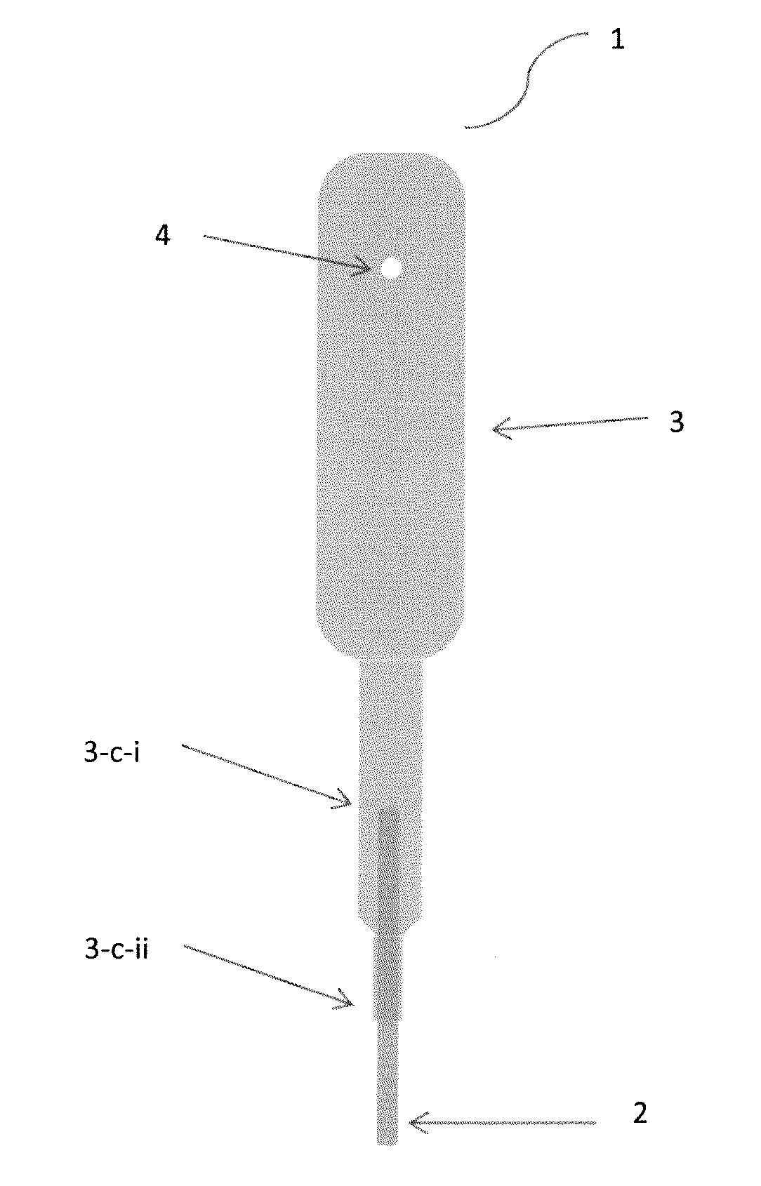
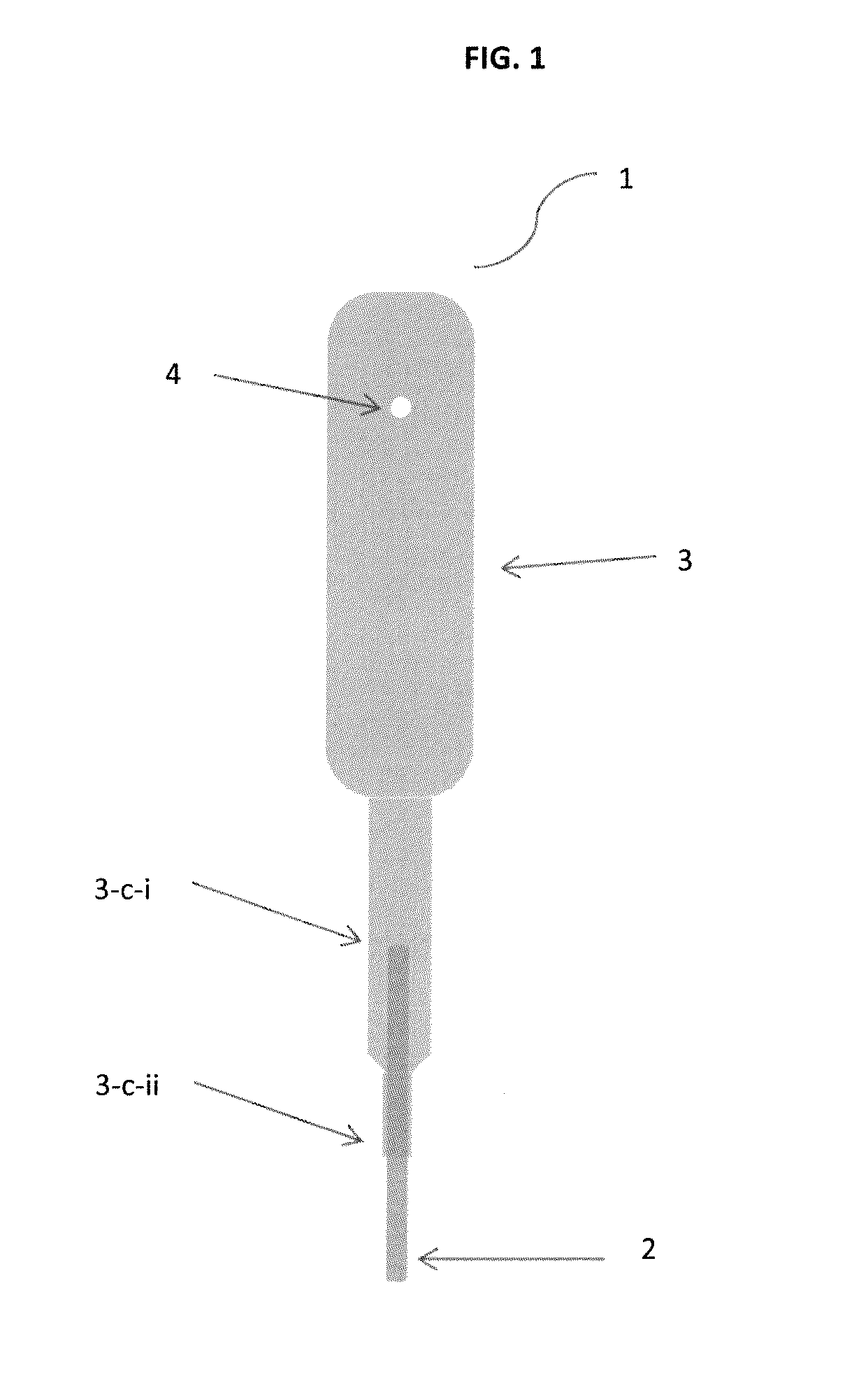
[0053]In embodiment 1, there is provided a pipette for delivering a precisely measured volume of liquid having:
[0054]a capillary tube (2) configured to draw liquid by capillary action, the capillary tube having a lower open end and an upper open end; and
[0055]a chamber (3) being structurally connected to the upper end of the capillary tube; the chamber having an orifice (4) in the upper portion of the chamber;
[0056]wherein,
[0057]the chamber extends to a middle tube extension (3-c-i) and continues to a bottom tube extension (3-c-ii); the bottom tube extension being integrally united to the capillary tube at the lower end of the bottom extension;
[0058]the orifice is on one sidewall of the chamber at a selected distance from the open end; and
[0059]the capillary tube has a diameter and a height of a predetermined measurement such that a precise collection of from about 0.1 μL to about 200 μL of a liquid is drawn by capillary action.
embodiment 2
[0060]In embodiment 2, there is provided a pipette for delivering a precisely measured volume of liquid having:
[0061]a capillary tube (2) configured to draw liquid by capillary action, the capillary tube having a lower open end and an upper open end; and
[0062]a chamber (3) being structurally connected to the upper end of the capillary tube; the chamber having an orifice (4) in the upper portion of the chamber;
[0063]wherein,
[0064]the chamber extends to a bottom tube extension (3-c-ii); the bottom tube extension being integrally united to the capillary tube at the lower end of the bottom extension;
[0065]the orifice is on one sidewall of the chamber at a selected distance from the open end; and
[0066]the capillary tube has a diameter and a height of a predetermined measurement such that a precise collection of from about 0.1 μL to about 200 μL of a liquid is drawn by capillary action.
[0067]In embodiment 3, there is provided a pipette according to embodiment 1 or 2, wherein the chamber i...
embodiment 4
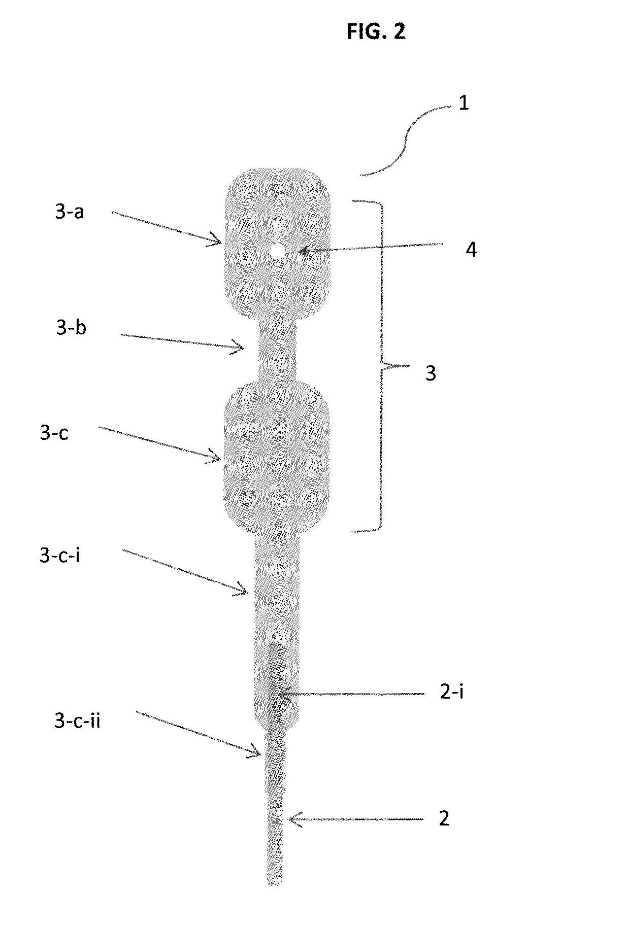
[0068]In embodiment 4, there is provided a pipette for delivering a measured volume of liquid having:
[0069]a capillary tube (2) configured to draw liquid by capillary action, the capillary tube having a lower open end and an upper open end; and
[0070]a chamber (3) being structurally connected to the upper end of the capillary tube, the chamber comprising an upper bulb and a lower bulb connected by a connection tube, wherein the upper bulb comprises an orifice;
[0071]wherein,
[0072]the chamber extends to a middle tube extension and continues to a bottom tube extension, the bottom tube extension being integrally united to the capillary tube at the lower end of the bottom extension;
[0073]the orifice is made through one sidewall of the upper bulb of the chamber; and
[0074]the capillary tube has a diameter and a height of a predetermined measurement such that a precise collection of from about 0.1 μL to about 200 μL of a liquid is drawn by capillary action.
PUM
 Abstract
Description
Claims
Application Information
 - R&D
- Intellectual Property
- Life Sciences
- Materials
- Tech Scout
- Unparalleled Data Quality
- Higher Quality Content
- 60% Fewer Hallucinations
Browse by: Latest US Patents, China's latest patents, Technical Efficacy Thesaurus, Application Domain, Technology Topic, Popular Technical Reports.
© 2025 PatSnap. All rights reserved.Legal|Privacy policy|Modern Slavery Act Transparency Statement|Sitemap|About US| Contact US: help@patsnap.com


