
Feedback amplifier

a technology of a feedback amplifier and a gain adjustment, applied in the field of optical communication systems, can solve the problems that the feedback amplifier cannot detect the burst packet input signal and the gain of a preamplifier cannot be freely adjusted, so as to prevent a distortion of the output waveform

Active Publication Date: 2014-07-03
ELECTRONICS & TELECOMM RES INST
View PDF6 Cites 5 Cited by
  • Summary
  • Abstract
  • Description
  • Claims
  • Application Information

AI Technical Summary

Benefits of technology

The patent text describes a feedback amplifier that includes a phase compensation circuit to prevent distortion in the output waveform caused by increased feedback current. The technical effect of this is improved amplification quality and accuracy.

Problems solved by technology

However, if the voltage level of a burst packet input signal is very low, the feedback amplifier may not detect the burst packet input signal.
However, since a control signal changes in response to an input signal, if there is a great difference between input signals, the gain of a preamplifier may not be freely adjusted.

Method used


Image

  • Feedback amplifier
  • Feedback amplifier
  • Feedback amplifier

Examples


Embodiment Construction

[0028]Preferred embodiments of the present invention will be described below in more detail with reference to the accompanying drawings. The present invention may, however, be embodied in different forms and should not be constructed as limited to the embodiments set forth herein. Rather, these embodiments are provided so that this disclosure will be thorough and complete, and will fully convey the scope of the present invention to those skilled in the art.

[0029]The present invention provides a feedback amplifier, as an optical communication system, adjusting a gain regardless of the size of an input signal in a passive optical network (PON) system. For example, a feedback amplifier may be disposed in an optical receiver.

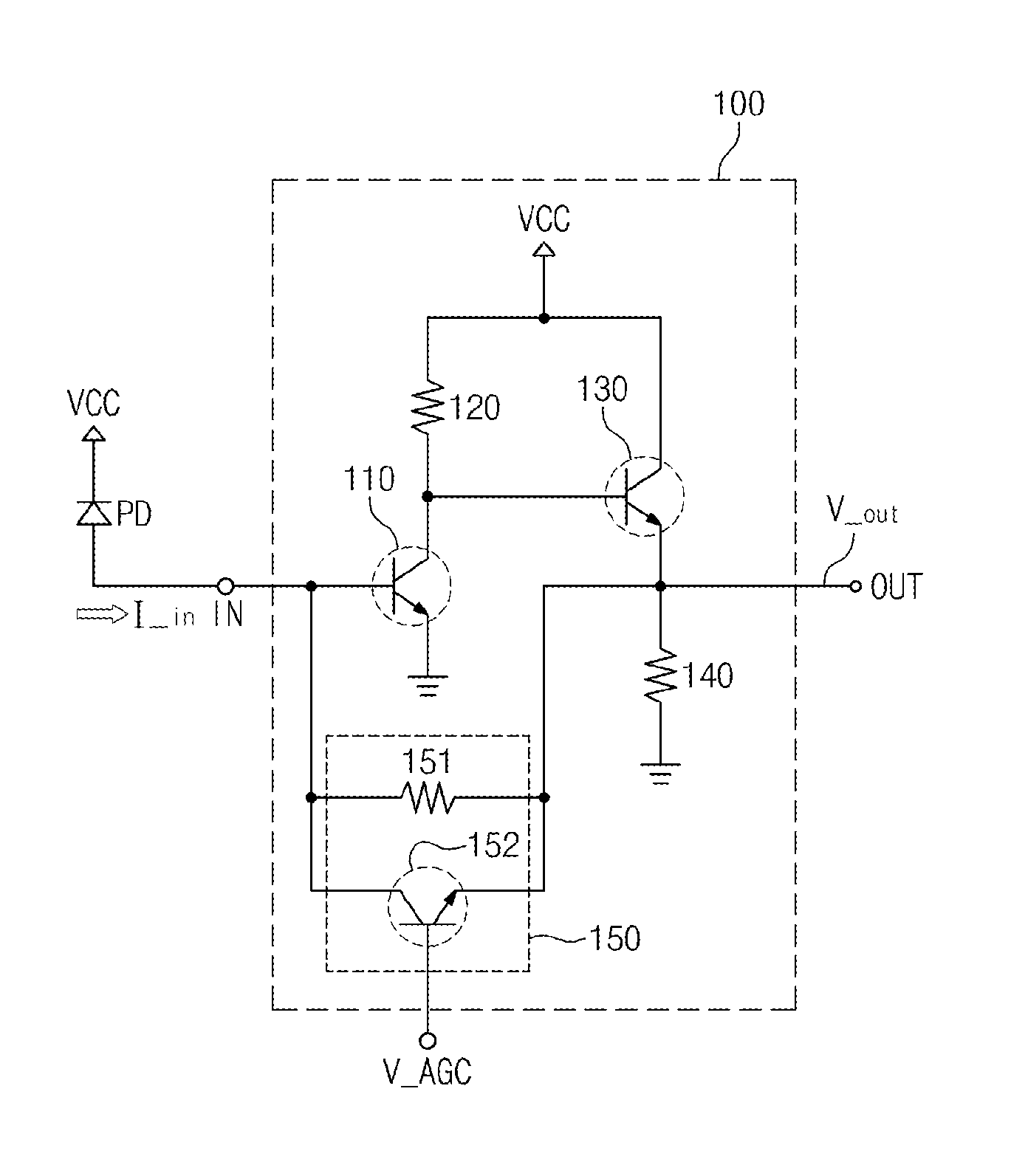
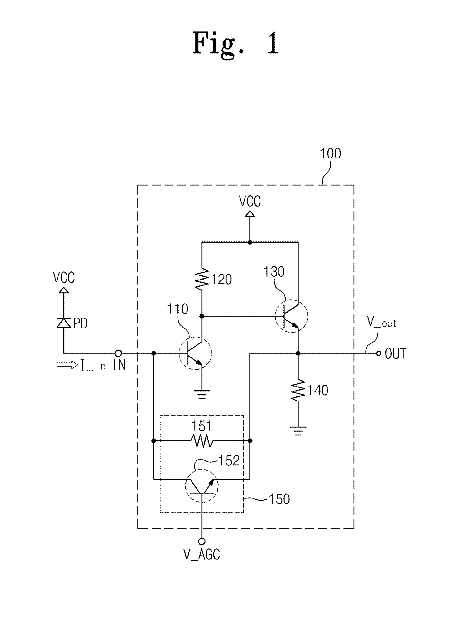
[0030]FIG. 1 is a schematic view of a typical feedback amplifier.

[0031]Referring to FIG. 1, a first feedback amplifier 100 is connected between an input terminal IN and an output terminal OUT. The input terminal IN is connected to a light receiving device connected ...


PUM


Abstract

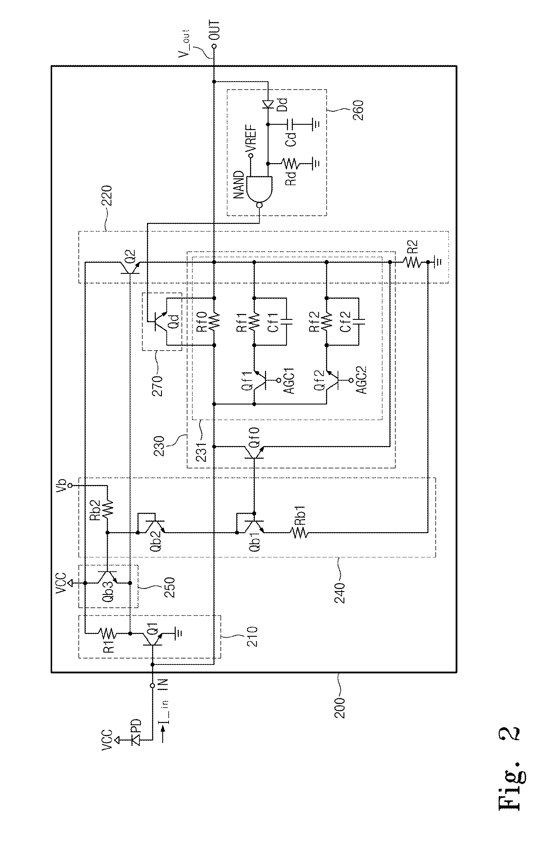
Provided is a feedback amplifier. The feedback amplifier includes: an amplification circuit unit amplifying a bust packet signal inputted from an input terminal and outputting the amplified voltage to an output terminal; a feedback circuit unit disposed between the input terminal and the output terminal and controlling whether to apply a fixed resistance value to a signal outputted to the output terminal; a packet signal detection unit detecting a peak value of a bust packet signal from the output terminal and controlling whether to apply the fixed resistance value; and a bias circuit unit generating a bias voltage, wherein the feedback circuit unit determines a feedback resistance value to change the fixed resistance value in response to at least one control signal and adjusts a gain by receiving the bias voltage.

Description

CROSS-REFERENCE TO RELATED APPLICATIONS[0001]This U.S. non-provisional patent application claims priority under 35 U.S.C. §119 of Korean Patent Application No. 10-2013-0000317, filed on Jan. 2, 2013, the entire contents of which are hereby incorporated by reference.BACKGROUND OF THE INVENTION[0002]The present invention disclosed herein relates to an optical communication system, and more particularly, to a feedback amplifier for receiving an input signal regardless of the size of the input signal.[0003]An optical access network evolves into the form of an optical multiple access using a passive optical network (PON). Such a passive optical network system uses an optical signal in a burst mode. An optical signal in the burst mode changes drastically and abruptly when a packet in one channel switches into a packet in another channel. Accordingly, an optical receiver requires a high reception sensitivity in addition to a wide dynamic range. A preamplifier is disposed at the first state...

Claims


Application Information

Patent Timeline
IPC IPC(8): H03G3/30
CPCH03G3/30H03G3/3084H03F3/08H03G1/0088H03G3/02H03G1/0047H03G11/02H03F1/30H03F1/34
Inventor LEE, SANG-HEUNGKIM, SEONG-ILKANG, DONG MINLIM, JONG-WONJU, CHULL WONYOON, HYUNG SUPMUN, JAE KYOUNGNAM, EUN SOO
Owner ELECTRONICS & TELECOMM RES INST
Learn More