
Thermally Conductive EMI Suppression Compositions

a technology of electromagnetic interference and composition, applied in the field of electromagnetic and radio frequency radiation suppression materials, can solve the problems of low overall electrical resistance, inability to adequately electrically isolate structures, and relatively low electrical resistivity of conventional electromagnetic and/or radio frequency interference suppression constructions, etc., to reduce and/or eliminate the transmission of radiation-sensitive equipment, soft and conformable, and low bulk modulus

Active Publication Date: 2014-07-03
HENKEL KGAA
View PDF4 Cites 12 Cited by
  • Summary
  • Abstract
  • Description
  • Claims
  • Application Information

AI Technical Summary

Benefits of technology

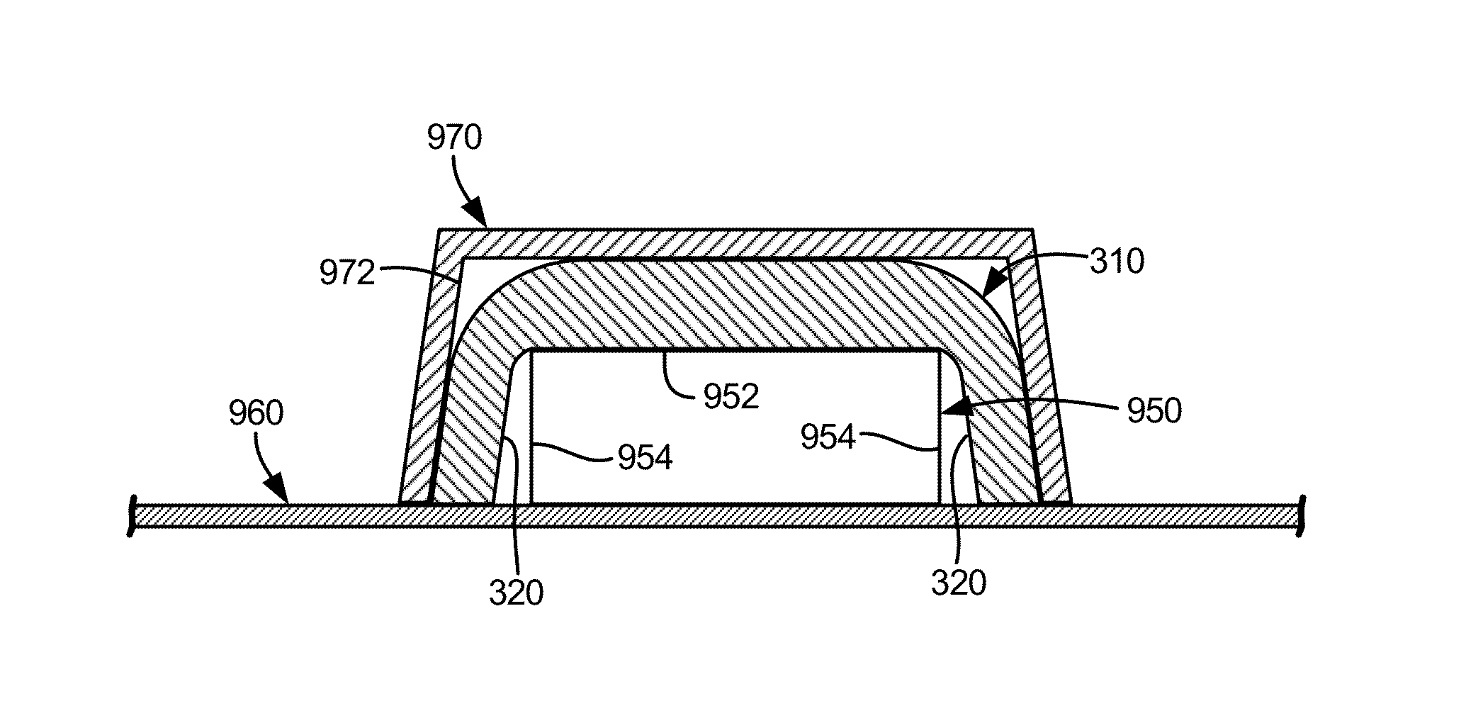
The present invention is an apparatus that reduces and eliminates electromagnetic and radio frequency interference between electronic components. It can be used in connection with integrated circuits, providing an insulative body that can be placed in direct contact with them while also suppressing interference. Additionally, the interface between the apparatus and the integrated circuits should have a low bulk modulus, making it soft and conformable.

Problems solved by technology

Such radiation can have the effect of causing electromagnetic interference (EMI) and / or radio frequency interference (RFI) with other electronic devices susceptible to and / or tuned to receive electromagnetic or radio frequency wave forms.
In doing so, the resultant compositions render the overall construction of low electrical resistance.
The relatively low electrical resistivity of conventional electromagnetic and / or radio frequency interference suppression constructions fail to adequately electrically isolate structures such as heat sinks that are operably coupled to the respective heat and interference radiation-generating electronic components via the interface.
Conventional EMI suppression materials also tend to be relatively rigid, thereby diminishing their effectiveness as thermal conductors.
The lack of compliance in conventional EMI suppression interfaces results in air gaps between the EMI suppression interface and the connected components.
Such air gaps act as a relative thermal barrier, and diminish the overall thermal conductivity of the interface.
Moreover, the relatively non-compliant conventional interface structures can cause damage to fragile electrical components in the assembly of the heat sinking apparatus, particularly as the heat sinks or external EMI shields are press-fit onto the EMI suppression interface.

Method used


Image

  • Thermally Conductive EMI Suppression Compositions
  • Thermally Conductive EMI Suppression Compositions
  • Thermally Conductive EMI Suppression Compositions

Examples


example

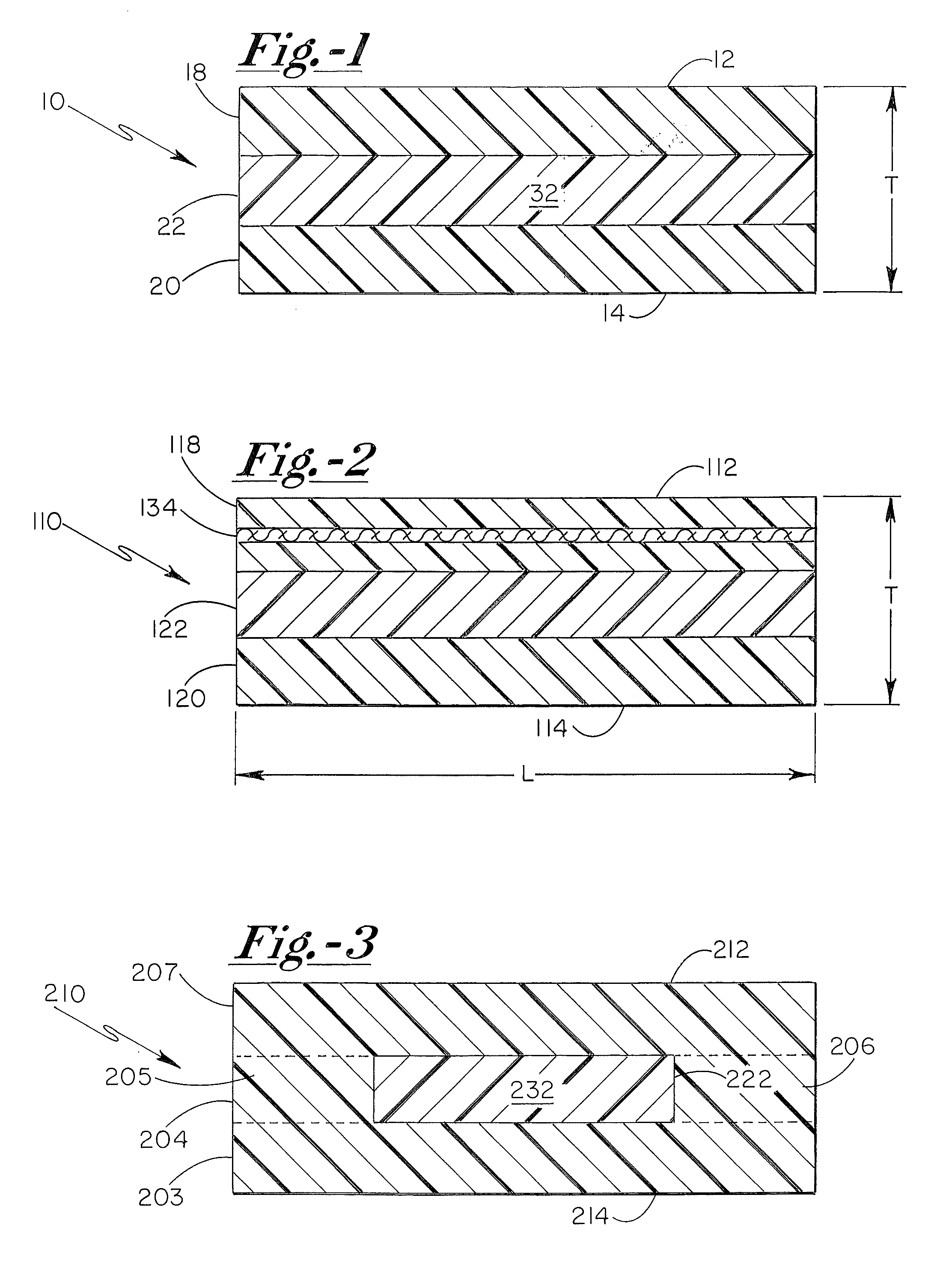
[0054]Two sample sets of interface pads were prepared, with a first set having a thickness dimension of 1 mm (“thin” samples), and the second sample set having a thickness dimension of 3 mm (“thick” sample set). The two sample sets were otherwise identical in composition, with the interface pads being prepared from the following composition:

VolumeIngredientDensity (g / ml)Wt. FractionFractionNusil Gel2 A Silicone Resin0.9700.09720.2160Nusil Gel2 B Silicone Resin0.9700.14580.3239512 Catalyst1.0200.00160.0034Steward MnZn Powder, 734015.1200.06320.0266Steward FeSi III6.1000.07540.0266Steward 992 Fe / Si / Al alloy7.1900.10510.0315Steward 987 Fe / Si / Al alloy6.8000.08390.0266TCP-8 Al powder2.7000.26740.2134TCP-3 Al powder / TCP4 Al2.7000.14580.1164powder (1:3.7 by wt)Carbon Black2.0000.01460.0157

[0055]The fillers were distributed in the silicone resins, which were coated on both sides of a 0.06 mm thick woven fiberglass layer, which was nominally in the midplane of the final construction.

[0056]Th...


PUM


Abstract

An interface pad for suppressing electromagnetic and radio frequency radiation includes first and second generally opposing sides which define a thickness therebetween, with the interface pad exhibiting thermal conductivity, electrical resistivity, and a hardness of between 10-70 Shore 00 at 20° C. The interface pad is capable of attenuating electromagnetic and / or radio frequency radiation that is commonly associated with interference of electronic components.

Description

FIELD OF THE INVENTION[0001]The present invention relates to electromagnetic and radio frequency radiation suppressing materials generally, and more particularly to thermally conductive interface products for use in connection with heat-generating electrical devices and heat sinking structures, wherein the interface products additionally act to suppress the propagation of electromagnetic and radio frequency radiation therethrough. The present invention further relates to methods for forming interface products having discrete functionality layers so as to enable electromagnetic and radio frequency interference suppression while providing an electrically isolative interface.BACKGROUND OF THE INVENTION[0002]Thermally conductive interface materials are widely utilized in the electronics industry for operably coupling heat-generating electronic components to heat-sinking structures. Most typically, such thermally conductive interface materials are utilized in connection with heat-generat...

Claims


Application Information

Patent Timeline
Patent Type & Authority Applications(United States)
IPC IPC(8): H05K9/00
CPCH05K9/0007Y10T428/25H05K7/20454H01L23/552H05K9/0029H05K9/003
Inventor MISRA, SANJAYTIMMERMAN, JOHNSEETHAMRAJU, KASYAP
Owner HENKEL KGAA
Learn More