
Method and System for a Portable Refrigerant Recovery Unit Load Controller

Active Publication Date: 2014-07-03
BOSCH AUTOMOTIVE SERVICE SOLUTIONS +1
View PDF2 Cites 15 Cited by
  • Summary
  • Abstract
  • Description
  • Claims
  • Application Information

AI Technical Summary

Benefits of technology

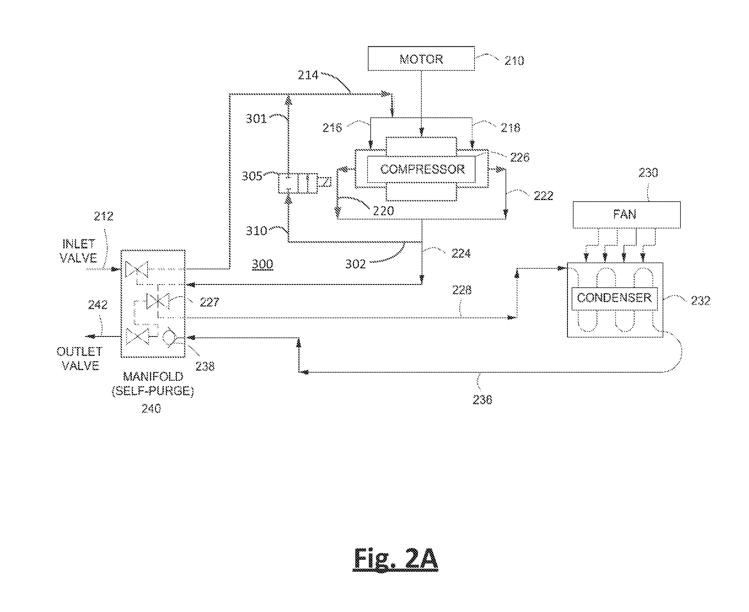
The patent describes a method for controlling the load of a refrigerant recovery unit. The method involves using service hoses to receive refrigerant from a refrigerant system and using a compressor to pump the refrigerant to the recovery unit. The method includes starting the compressor and monitoring the current drawn by its motor. When the current exceeds a predetermined threshold, a solenoid valve is activated to open a flow path in a compressor bypass loop line, which decreases the current drawn by the compressor motor. This helps to control the load on the refrigerant recovery unit.

Problems solved by technology

However, motor design specifications are also frequently limited by size, weight, physical footprint, and cost of the units.
However, operation complications during the startup of the unit or during normal operation when refrigerant flow restrictions occur often bring about undesired field solutions to get the refrigerant recovery units to start up or continue to work.

Method used


Image

  • Method and System for a Portable Refrigerant Recovery Unit Load Controller
  • Method and System for a Portable Refrigerant Recovery Unit Load Controller
  • Method and System for a Portable Refrigerant Recovery Unit Load Controller

Examples


Embodiment Construction

[0017]In some aspects of the disclosure, the load controller can be used to decrease the current / pressure load placed on the compressor's motor during activation and / or during abnormal refrigerant flow, and as a result, may lower the torque requirements of the motor. Moreover, because higher load requirements at these stages can result in either a need in specifying motors with higher torque capabilities and energy consumption or in less than ideal field solutions to reduce the pressure load, the disclosure provides for a safe solution that can keep lower motor torque specification requirements, and in doing so, conserving energy.

[0018]In some embodiments of the disclosure, a solenoid valve of the load controller of the system can be synchronized to operate with the start relay of the motor. The solenoid valve can be used to open and close a refrigerant flow path in the compressor bypass loop line to lower the torque required when the start relay of the motor is activated due to a s...


PUM


Abstract

A system and methods associated therewith for providing a load controller for a refrigerant recovery unit are disclosed. The load controller can be controlled to operate when the current drawn by the motor increases due to pressure changes caused by abnormal refrigerant flow or during activation of the motor in order to lower the pressure. In some aspects of the present disclosure, the load controller can lower the pressure by recirculating some of the pressure load through the opening of a compressor bypass loop line. In some embodiments, the current / pressure load may be monitored during the operation of the refrigerant recovery unit and set to act as an emergency shut off and alert system to the user when the system malfunctions.

Description

FIELD OF THE DISCLOSURE[0001]The disclosure generally relates to a refrigerant recovery unit. More particularly, the disclosure relates to a load controller system and method associated therewith.BACKGROUND OF THE DISCLOSURE[0002]Refrigerant recovery units are used for the maintenance and servicing of refrigerant systems including, for example, air conditioning systems. Refrigerant recovery units include a compressor with a motor that is used to recover and recharge the refrigerant from the air conditioning system. The design specifications of the compressor's motor must be so that the torque capabilities, among other sizing factors, of the motor are sufficient for the unit to operate accordingly. However, motor design specifications are also frequently limited by size, weight, physical footprint, and cost of the units.[0003]In addition to these limitations, energy preservation is also of utmost importance. Conventional energy efficient system designs that include lower torque motor...

Claims


Application Information

Patent Timeline
IPC IPC(8): F25B49/02
CPCF25B49/02F25B27/005F25B49/00F25B2700/04F25B45/00F25B2345/002F25B2345/003F25B2345/0051F25B2400/0401F25B2500/26F25B2600/026F25B2700/151
Inventor LUNDBERG, DYLANMCMASTERS, MARK
Owner BOSCH AUTOMOTIVE SERVICE SOLUTIONS
Learn More