
Discectomy devices and methods

Inactive Publication Date: 2014-06-26
EXPANDING INNOVATIONS INC
View PDF5 Cites 62 Cited by
  • Summary
  • Abstract
  • Description
  • Claims
  • Application Information

AI Technical Summary

Benefits of technology

The patent describes a device with a tool at the end that is used to dilate tissues. The tool has a surface that is angled, which helps to spread the tissues. The device also has an electric motor to power it. A power source is located in the handle to provide power to the motor. The device has an impeller and a tubular member that is connected to the impeller and the motor. These technical features make it easier to use the device for surgical procedures.

Problems solved by technology

Compression of these neural structures can lead to pain, parasthesias, weakness, urine and fecal incontinence and other neurological symptoms that can substantially impact basic daily activities and quality of life.

Method used


Image

  • Discectomy devices and methods
  • Discectomy devices and methods
  • Discectomy devices and methods

Examples


Embodiment Construction

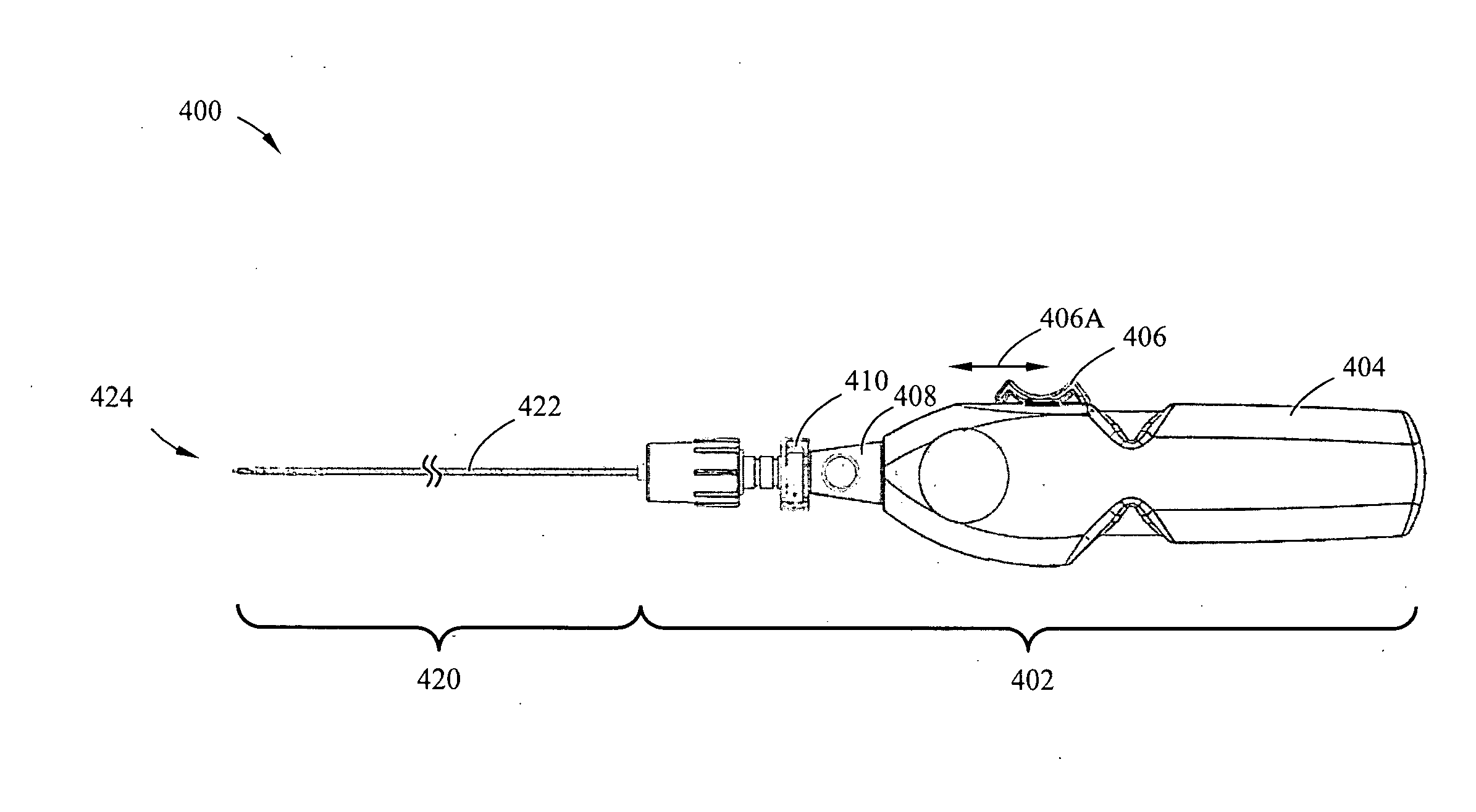
[0018]Tissue removal devices and methods, such as discectomy devices and methods, are described herein. In certain variations, a discectomy device may be introduced into a disc via dilation of an access hole through the annulus, such that it may not be necessary to cut the annulus to access the disc. In some variations, a discectomy device may comprise a relatively long auger, and / or an impeller that breaks down acquired tissue during a procedure. During use, the auger and impeller may effect a plunging motion that allows for relatively rapid tissue aspiration and aggressive tissue cutting, without stretching the annulus. Additionally, it may not be necessary to make several passes into and out of a patient to remove tissue, using devices and methods described herein. By limiting cutting, stretching and / or the number of passes through tissue, scarring of annular tissue, reherniation and / or leakage of healthy nucleus tissue may be avoided, and / or annulus healing time may be reduced.

[...


PUM


Abstract

A tissue removal device may comprise a handle portion and a tissue removal mechanism coupled to the handle portion. The tissue removal mechanism may include a tubular member having a lumen therethrough and an elongate member rotatably and slidably disposed within the lumen of the tubular member. A proximal end of the elongate member may be coupled to a drive source to impart rotational movement thereof. A distal end of the elongate member may include an impeller for cutting tissue. The elongate member may be configured to exit the distal end of the lumen of the first tubular member, such that the distal end of the second tubular member is distal to the distal end of the first tubular member. The impeller may include a blunt distal end to minimize undesirable tissue damage when the distal end of the elongate member is distal to the distal end of the tubular member.

Description

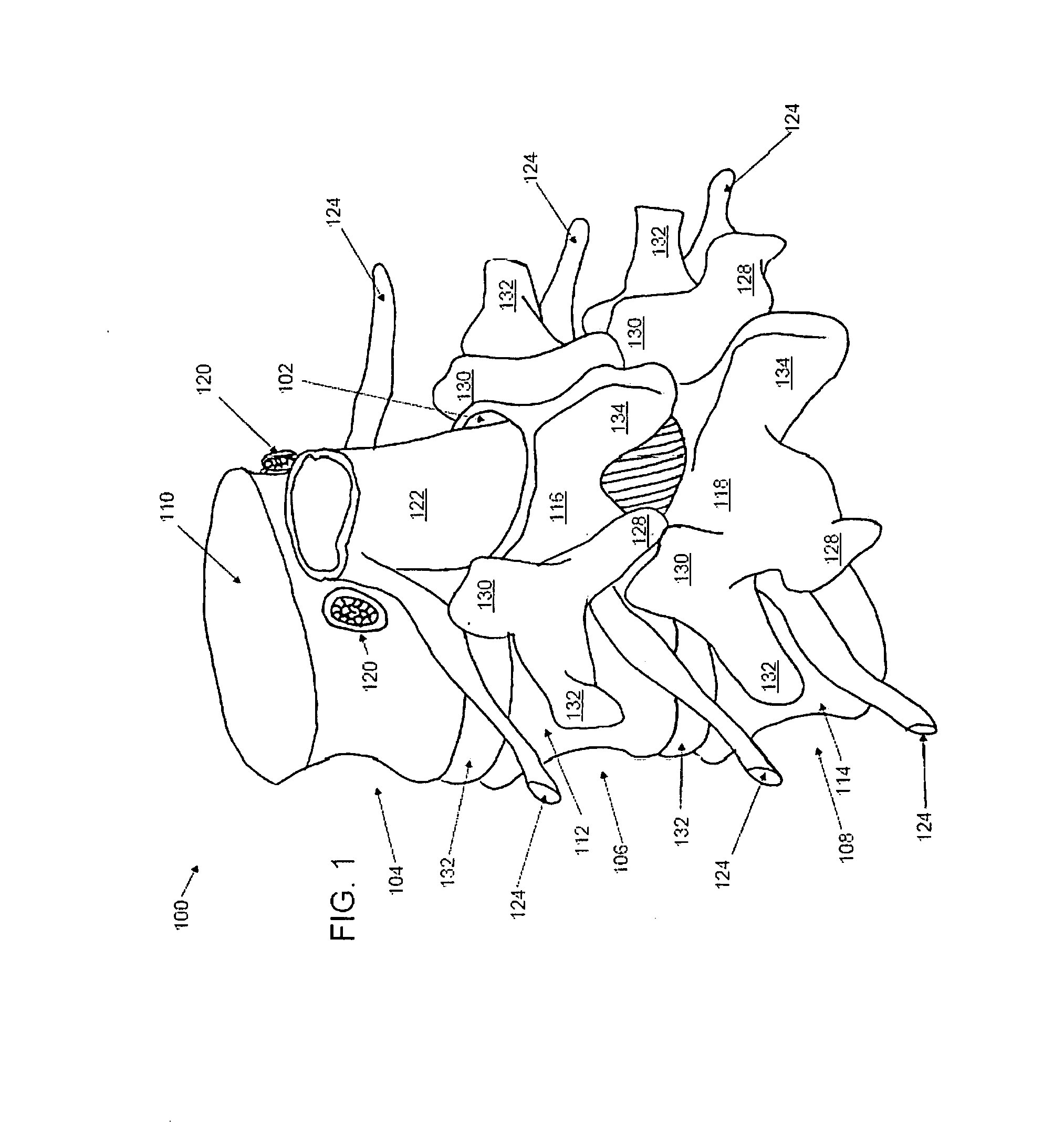
[0001]This application claims priority to U.S. Provisional Application Ser. No. 61 / 740,171, entitled “Discectomy Devices and Methods,” filed Dec. 20, 2012, which application is incorporated herein by reference in its entirety.BACKGROUND[0002]Vertebral disc herniation is a common disorder where a portion of a vertebral disc, a cushion-like structure located between the vertebral bodies of the spine, bulges out or extrudes beyond the usual margins of the disc and the spine. Disc herniation is believed to be the result of excessive loading on the disc in combination with weakening of the annulus due to such factors as aging and genetics. Disc herniation and other degenerative disc diseases are also associated with spinal stenosis, a narrowing of the bony and ligamentous structures of the spine. Although disc herniation can occur anywhere along the perimeter of the disc, it occurs more frequently in the posterior and posterior-lateral regions of the disc, where the spinal cord and spina...

Claims


Application Information

Patent Timeline
IPC IPC(8): A61B17/3205
CPCA61B17/32002A61B2017/00261A61B2017/00685
Inventor DIAS, MARKMIREL, ALMAY, ROBERT
Owner EXPANDING INNOVATIONS INC
Learn More