Eureka AIR delivers breakthrough ideas for toughest innovation challenges, trusted by R&D personnel around the world.

Substrate attachment device of display device and method for manufacturing display device using the same

a technology of display device and substrate, which is applied in the manufacture of electric discharge tubes/lamps, identification means, instruments, etc., can solve the problems of no lamination equipment for attaching a curved substrate to the display panel, the bubble generation between the display panel and the curved substrate, and the inability to easily remove the bubbles

Active Publication Date: 2014-06-26
LG DISPLAY CO LTD
View PDF7 Cites 16 Cited by
  • Summary
  • Abstract
  • Description
  • Claims
  • Application Information

AI Technical Summary

Benefits of technology

The patent describes a device and method for attaching a cover substrate with a curved surface to a display panel for manufacturing a display device. The device includes a guide unit, a first support unit, and a second support unit. The method involves forming subpixels on a flexible substrate, attaching a protection film to form a display panel, loading the cover substrate onto the first support unit, transferring the first and second support units to a process region, and rotating a roller unit to attach the cover substrate onto the display panel when the first and second support units approach the process region. The technical effects of this device and method include improved manufacturing efficiency and accuracy of display device attachment.

Problems solved by technology

However, there is no lamination equipment for attaching a curved cover substrate to the display panel so as to manufacture the curved display panel in a related art.
However, when the curved cover substrate is attached to the display panel using the related art equipment, bubbles are generated between the display panel and the curved cover substrate.
Even when a defoamation process is performed on the bubbles generated between the display panel and the curved cover substrate, the bubbles are not easily removed.

Method used


Image

  • Substrate attachment device of display device and method for manufacturing display device using the same
  • Substrate attachment device of display device and method for manufacturing display device using the same
  • Substrate attachment device of display device and method for manufacturing display device using the same

Examples


first embodiment

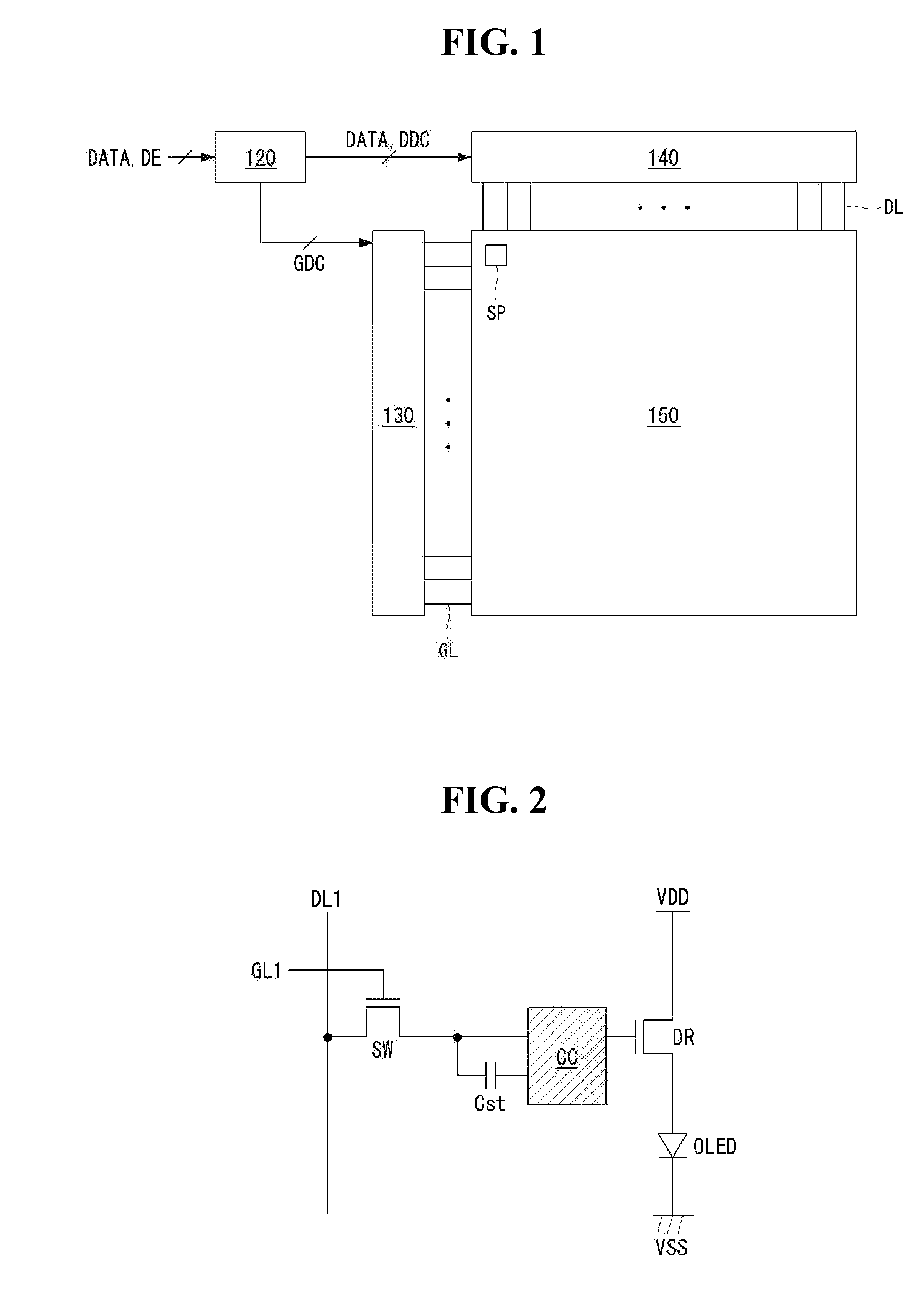
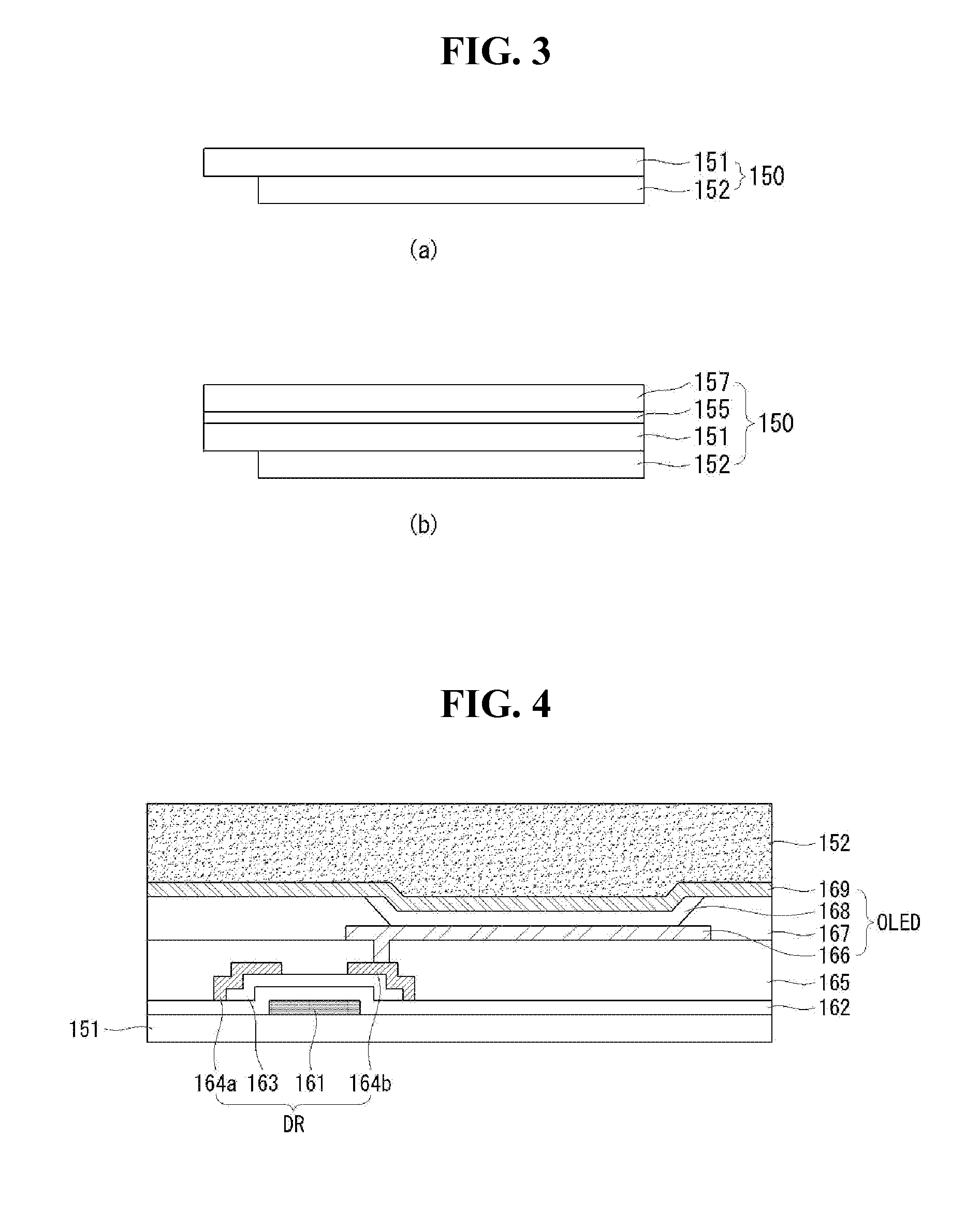
[0026]FIG. 1 is a schematic block diagram of a flexible display according to an exemplary embodiment of the invention. FIG. 2 illustrates an example of a subpixel shown in FIG. 1. FIG. 3 is a cross-sectional view of a display panel shown in FIG. 1. FIGS. 4 and 5 illustrate examples of a cross-sectional structure of a subpixel configured as an organic light emitting element. FIG. 6 is a cross-sectional view of a curved display panel according to the embodiment of the invention.

[0027]As shown in FIG. 1, the flexible display according to the embodiment of the invention includes a timing controller 120, a gate driver 130, a data driver 140, and a display panel 150.

[0028]The timing controller 120 collects extended display identification data (EDID) including a resolution, a frequency, timing information, etc. of the display panel 150 or compensation data from an external memory through I2C interface, etc. The timing controller 120 outputs a gate timing control signals GDC for controlling...

second embodiment

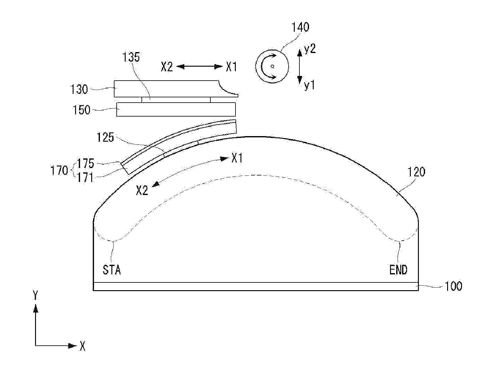
[0058]FIG. 9 schematically illustrates a configuration of a substrate attachment device of a display device according to a second embodiment of the invention. FIG. 10 illustrates a lamination process using the substrate attachment device of the display device according to the second embodiment of the invention.

[0059]The substrate attachment device of the display device according to the second embodiment of the invention includes a base unit 100, a guide unit 121, a first support unit 125, a second support unit 130, and a roller unit 140.

[0060]The guide unit 121 is installed on a fixing unit 101 vertically protruding from the base unit 100. The guide unit 121 includes a pair of caterpillar rails. The pair of caterpillar rails include track rails and wheels. The pair of caterpillar rails have a semicircular curve shape and are fixed to the fixing unit 101. The pair of caterpillar rails receive electric power from a motor or a gear, etc. and rotate.

[0061]The first support unit 125 is i...

third embodiment

[0068]FIGS. 11 and 12 schematically illustrate a configuration of a substrate attachment device of a display device according to a third embodiment of the invention. FIG. 13 illustrates a lamination process using the substrate attachment device of the display device according to the third embodiment of the invention.

[0069]The substrate attachment device of the display device according to the third embodiment of the invention includes a base unit 100, a motor unit 115, an operation unit 110, a rotation shaft 117, a movement unit 118, a guide unit 120, a first support unit 125, a second support unit 130, and a roller unit 140.

[0070]The operation unit 110 is a device for operating the motor unit 115, the movement unit 118, the guide unit 120, the first support unit 125, the second support unit 130, and the roller unit140. A position of the operation unit 110 is not limited to FIGS. 11 and 12.

[0071]The motor unit 115 transfers a rotation force to the rotation shaft 117 and rotates so th...


PUM


Abstract

A substrate attachment device of a display device and a method for manufacturing the display device using the same are disclosed. The substrate attachment device of the display device includes a guide unit which is curvedly disposed, a first support unit which moves forward and backwards along the guide unit and transfers a cover substrate having a curved surface, a second support unit which is disposed on the guide unit, moves forward and backwards, and transfers a display panel, and a roller unit which rotates so that the cover substrate having the curved surface is attached to the display panel.

Description

[0001]This application claims the benefit of priority of Korean Patent Application No. 10-2012-0152785 filed on Dec. 26, 2012, the entire contents of which is incorporated herein by reference for all purposes as if fully set forth herein.BACKGROUND OF THE INVENTION[0002]1. Field of the Invention[0003]Embodiments of the invention relate to a substrate attachment device of a display device and a method for manufacturing the display device using the same.[0004]2. Discussion of the Related Art[0005]The market of flat panel displays used as media between users and information is increasing with the development of information technology. Hence, the use of flat panel displays, such as an organic light emitting display, a liquid crystal display (LCD), an electrophoretic display, and a plasma display panel (PDP), is increasing.[0006]Out of the above flat panel displays, the organic light emitting display, the liquid crystal display, and the electrophoretic display may be used as a flexible d...

Claims


Application Information

Patent Timeline
IPC IPC(8): H01J9/24
CPCH01J9/241G02F1/1303G02F1/133305G09F9/00H01L21/00
Inventor KO, YOUNGJO
Owner LG DISPLAY CO LTD
Why Eureka
Eureka Blog
Learn More