
Display apparatus and method for manufacturing the same

a technology for display devices and manufacturing methods, applied in the manufacture of electrode systems, electric discharge tubes/lamps, instruments, etc., can solve the problems of reducing the thickness of lcd devices or changing their design, attracting much attention, and limiting the development of new designs of display devices. , to achieve the effect of front border widths, minimizing light leakage, and minimizing the thickness of devices

Active Publication Date: 2014-06-26
LG DISPLAY CO LTD
View PDF1 Cites 6 Cited by
  • Summary
  • Abstract
  • Description
  • Claims
  • Application Information

AI Technical Summary

Benefits of technology

The present invention provides a display device and a method of manufacturing the same that can reduce device thickness, minimize front border width, and remove step height. Additionally, the invention maintains a constant interval between the display panel and guide frame to absorb impact and reduces light leakage from the display panel.

Problems solved by technology

However, among such flat panel display devices, LCD devices are easily manufactured, have good drivability, realize a high-quality image, and thus are attracting much attention.
Due to these reasons, there are limitations in slimming display devices and developing the new designs of the display devices.
As described above, display devices of the related art necessarily use the front set cover and rear set cover as well as the lower case and front case, and consequently, there are limitations in reducing the thicknesses of LCD devices or changing their designs.
For this reason, the thicknesses of display devices inevitably become thicker, and moreover, the border widths of the display devices enlarge.
In addition, it is difficult to realize various innovative designs due to a step height in a border portion between a cover and the display panel.

Method used


Image

  • Display apparatus and method for manufacturing the same
  • Display apparatus and method for manufacturing the same
  • Display apparatus and method for manufacturing the same

Examples


Embodiment Construction

[0034]Hereinafter, a display device and a method of manufacturing the same according to the present invention will be described in detail with reference to the accompanying drawings.

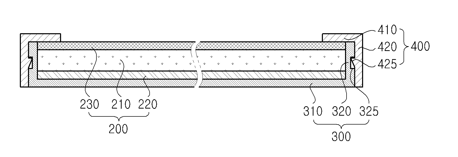
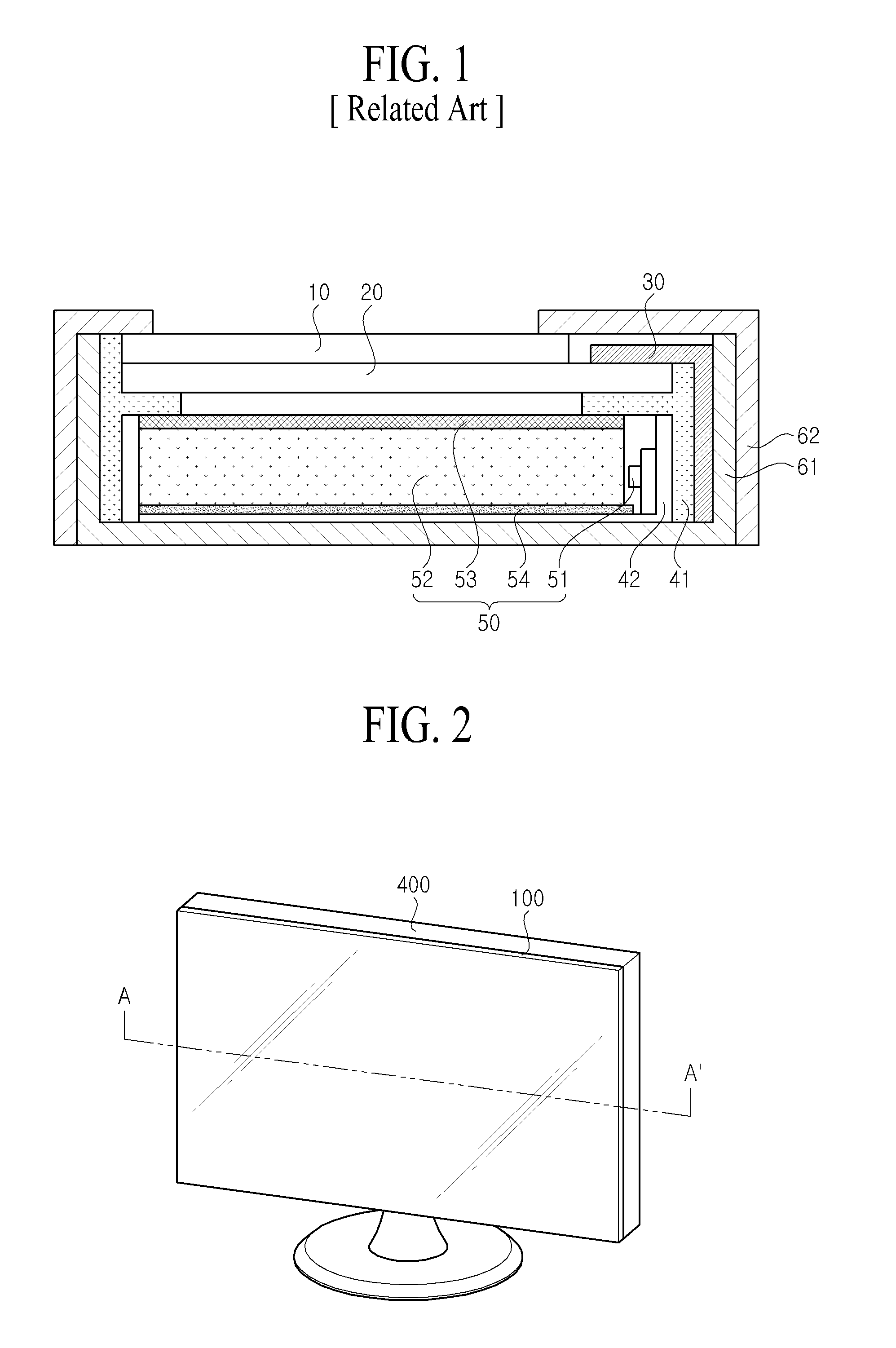
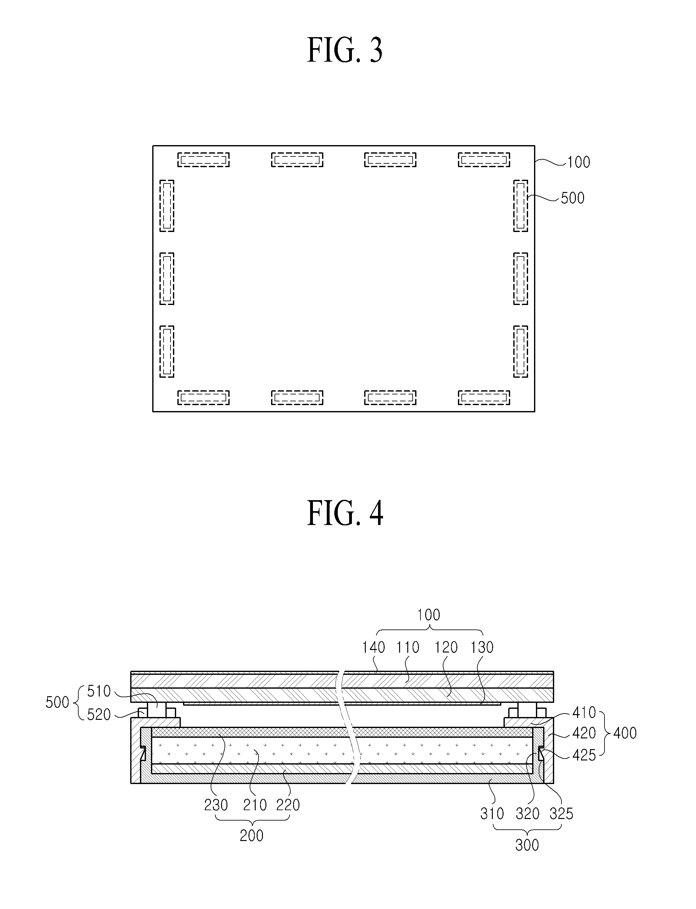
[0035]FIG. 2 is a perspective view illustrating an exemplary embodiment of a display device according to the present invention. FIG. 3 is a plan view illustrating an embodiment of the display device of the present invention of FIG. 2. FIG. 4 is a sectional view illustrating an embodiment of a sectional plane taken along line A-A′ of the display device of the present invention of FIG. 2. FIG. 5 is a view illustrating an embodiment of a structure at a top of a guide frame according to the present invention.

[0036]As illustrated in FIGS. 2 to 5, the display device according to an embodiment of the present invention may include a display panel 100, a backlight unit 200, a cover member 300, a guide frame 400, and a coupling member 500.

[0037]The display panel 100 may include an upper substrate 110, a lower subs...


PUM

PropertyMeasurementUnit
heightaaaaaaaaaa
viscosityaaaaaaaaaa
temperatureaaaaaaaaaa

Abstract

A display apparatus includes a display panel including an upper substrate and a lower substrate coupled to a rear surface of the upper substrate; a guide frame supporting the display panel, and a coupling member coupling the guide frame to the display panel. The coupling includes a main adhesive adhering the guide frame to the display panel, and a sub adhesive adhered to the guide frame adjacent to the main adhesive. Accordingly, the display panel can more readily absorb an impact applied thereto, thus enhancing the stability of the display panel.

Description

CROSS-REFERENCE TO RELATED APPLICATIONS [0001]This application claims the benefit of the Korean Patent Application Nos. 10-2012-0153726 filed on Dec. 26, 2012, and 10-2013-0155106 filed on Dec. 13, 2013, which are hereby incorporated by reference in their entirety as if fully set forth herein.BACKGROUND [0002]1. Field of the Invention[0003]The present invention relates to a display device and a method of manufacturing the same.[0004]2. Discussion of the Related Art[0005]Recently, flat panel display devices that can decrease weight and volume compared to cathode ray tubes (CRTs) are being developed. Liquid crystal display (LCD) devices, plasma display panels (PDPs), field emission display (FED) devices, and light emitting display devices are actively being researched as flat type display devices. However, among such flat panel display devices, LCD devices are easily manufactured, have good drivability, realize a high-quality image, and thus are attracting much attention.[0006]In term...

Claims


Application Information

Patent Timeline
Patent Type & Authority Applications(United States)
IPC IPC(8): G02F1/1333
CPCG02F1/133308G02F2202/28G02F1/133317
Inventor SHIN, SUNG-EUIJANG, CHANG SOO
Owner LG DISPLAY CO LTD
Learn More