
Bond beam and block joist

a technology of bonding beams and joists, which is applied in the direction of building roofs, building components, constructions, etc., can solve the problems of high construction cost, high carpentry skill level,

Inactive Publication Date: 2014-06-26
EDWARDS DOUGLAS
View PDF6 Cites 0 Cited by
  • Summary
  • Abstract
  • Description
  • Claims
  • Application Information

AI Technical Summary

Benefits of technology

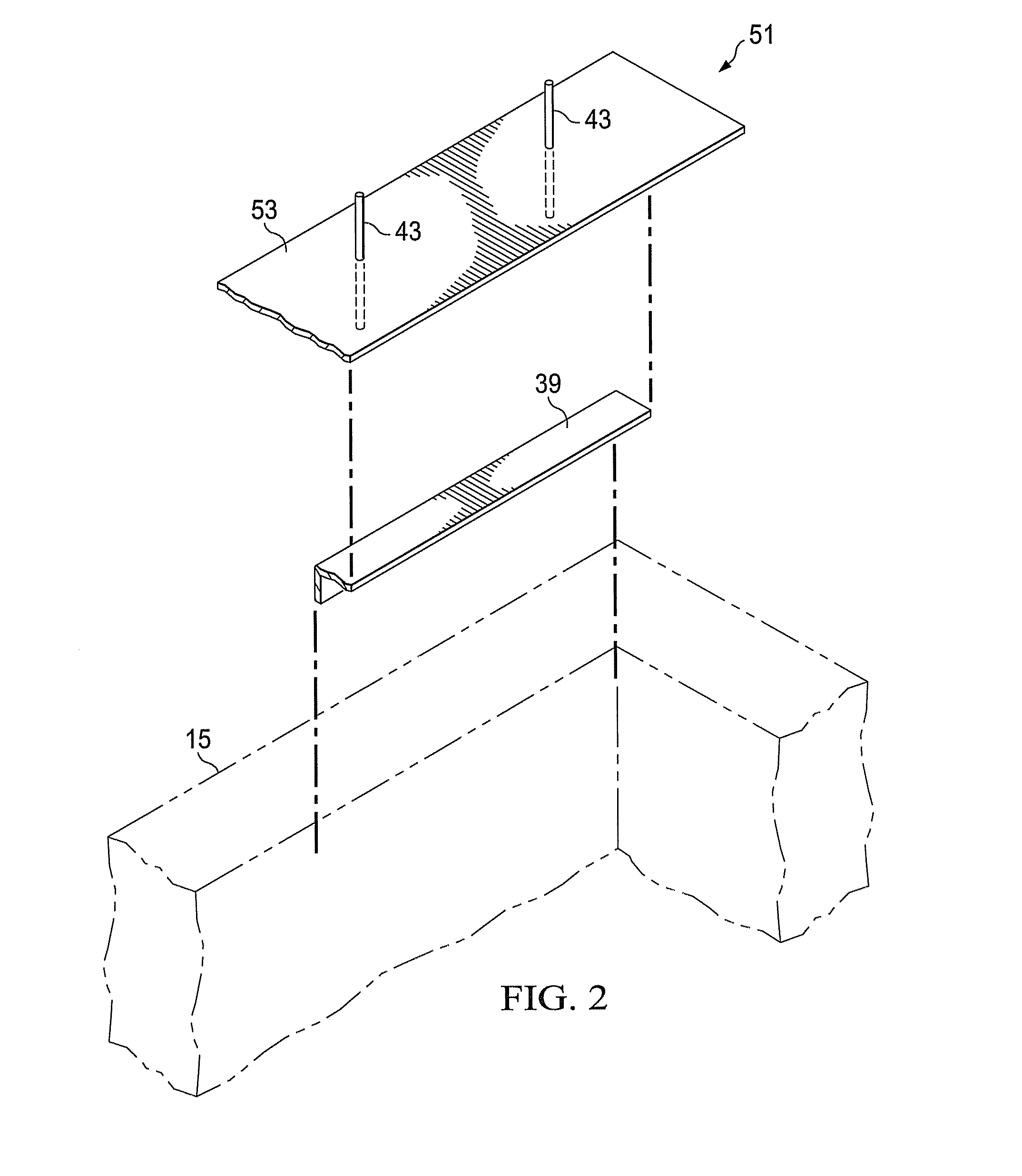
The patent describes a building made up of stacked blocks with cavities aligned vertically, and joists that support a horizontal roof or floor. The joists have a vertical plate with an angle piece at each end, which is attached to a vertical wall. The angle pieces extend laterally from the vertical plate and have a width that comprises the thickness of the vertical plate and the lateral extension of the angle piece. Each end has a horizontal end plate that extends longitudinally from the respective end, with at least one pin extending vertically down. The end plates have a width that is wider than the angle piece and the vertical plate, and are located on the walls. The building also has horizontal blocks on top of the joists, forming a top surface. In another aspect, the patent describes the use of an angle piece on both joists to support additional weight. The joists are shaped like a "T" in transverse cross-section. The end plates can be interior or exterior, and are designed to fit into cavities in blocks. The building also has a bond beam along a perpendicular wall. The technical effects of the patent include improved load-bearing capacity, stability, and resistance to seismic and wind loads.

Problems solved by technology

This type of construction requires a relatively high level of skill in carpentry and also expensive construction materials.

Method used


Image

  • Bond beam and block joist
  • Bond beam and block joist
  • Bond beam and block joist

Examples


Embodiment Construction

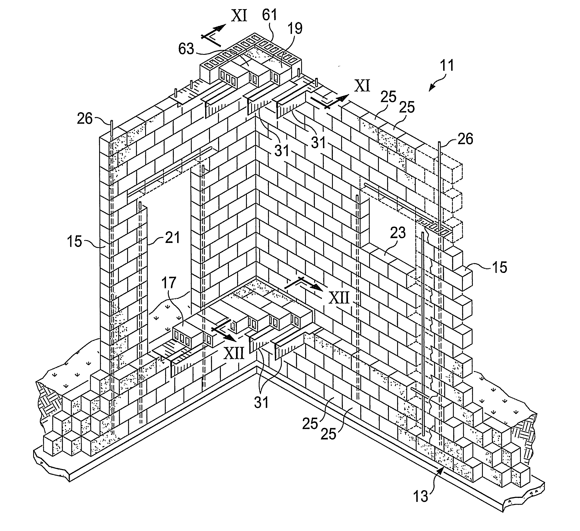
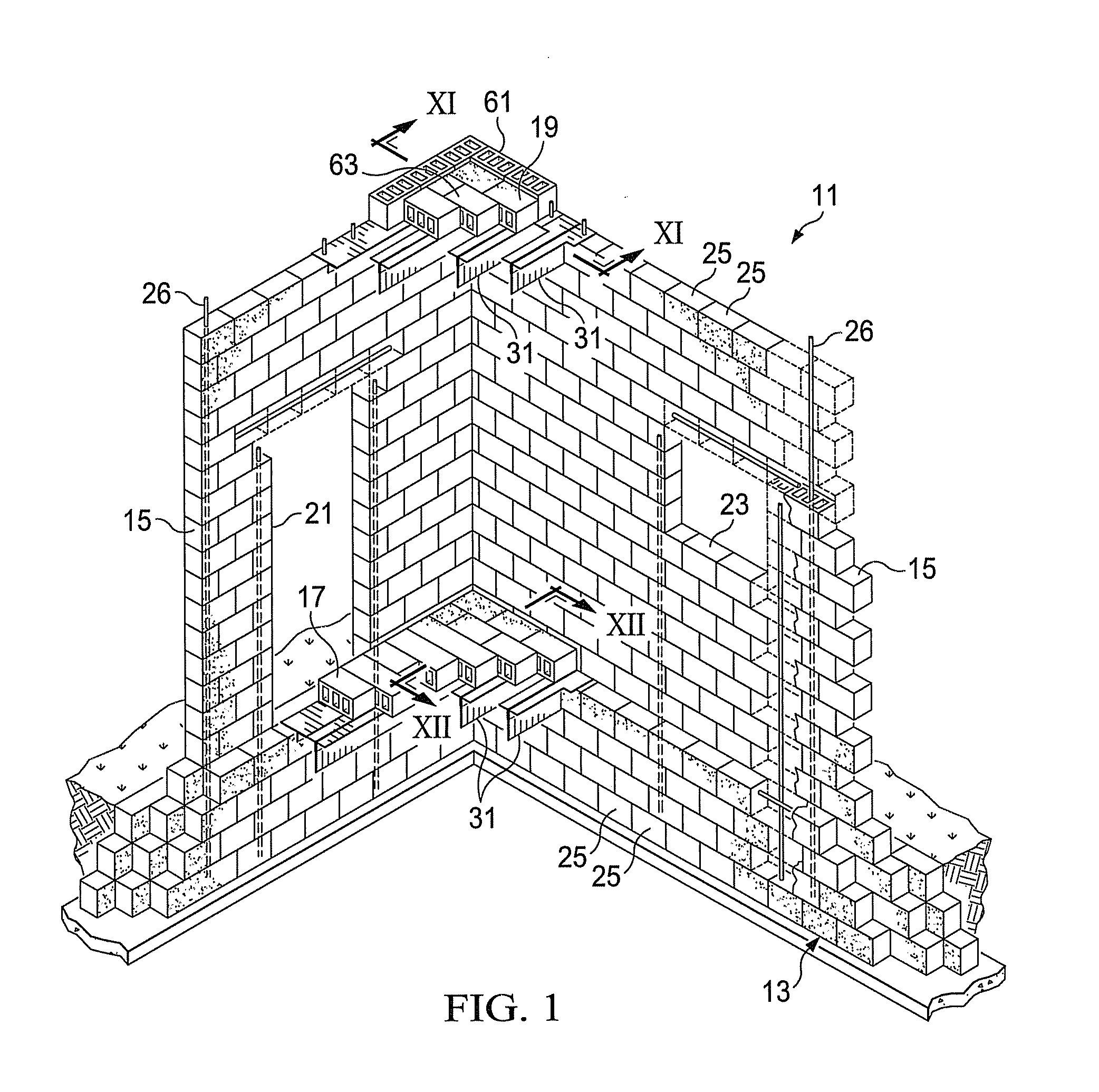
[0031]In FIG. 1, part of a building 11 is shown. The building has a foundation 13, walls 15, a floor 17 and a roof 19. The interior of the building can have one or more rooms. The walls 15 have doorways 21 and window openings 23. The walls 15 and foundation 13 are formed from concrete or cement blocks 25. Such blocks 25 are typically rectangular with holes or cavities 27 (see FIG. 11) therethrough. When building the walls 15 with the blocks, the cavities 27 are vertically oriented so that the cavities of one block align with the cavities located above and below adjacent blocks. Typically vertical bars 26 are inserted into the walls so as to extend into the cavities of plural rows of blocks. The blocks 25 can be the type that are conventional and commercially available, which blocks can be mortared together to build the walls. Alternatively, the blocks 25 could be mortarless as described in my previous patent application Publication No. 2008 / 0060313, the complete disclosure which is ...


PUM


Abstract

A building has walls built from blocks with cavities. Roofs and floors are formed from joists extending between walls. Each joist has a vertical plate, an angle piece located on each side of the vertical plate and end plates. The end plates bear on the wall blocks. Pins extend from the end plates into cavities of the wall blocks. Bond beams can be positioned on walls parallel to the joist. Horizontal blocks are laid across the joists to form a roof or floor.

Description

[0001]This application is a continuation-in-part application of application Ser. No. 29 / 442,161, filed Dec. 26, 2012.FIELD OF THE INVENTION[0002]The present invention relates to buildings and structures made from blocks and joists.BACKGROUND OF THE INVENTION[0003]There is a need in the United States of America and abroad for low cost housing. Traditionally, permanent housing is of stick and frame construction involving the use of lumber, such as 2×4's, to make the walls and larger lumber boards for joists and roofing. This type of construction requires a relatively high level of skill in carpentry and also expensive construction materials.[0004]As an alternative to such construction, concrete or cement block construction has been explored. Cement blocks are relatively low cost and can be made in molds. While previous efforts to use cement blocks have made progress, costs could further be reduced, particularly in constructing horizontal structures such as roofs and floors.SUMMARY OF ...

Claims


Application Information

Patent Timeline
Patent Type & Authority Applications(United States)
IPC IPC(8): E04B1/38E04B1/04
CPCE04B1/04E04B1/38E04B5/08E04B5/10E04C2003/0413E04C2003/046
Inventor EDWARDS, DOUGLAS
Owner EDWARDS DOUGLAS
Learn More