
Mobile geolocation

a mobile geolocation and reference technology, applied in the direction of location information based services, instruments, synchronisation arrangements, etc., can solve the problems of difficult to obtain these known signatures, limited differential power techniques, and relatively infrequent power measurements in event-driven technologies such as l

Active Publication Date: 2014-06-19
VIAVI SOLUTIONS UK
View PDF8 Cites 49 Cited by
  • Summary
  • Abstract
  • Description
  • Claims
  • Application Information

AI Technical Summary

Benefits of technology

The patent text describes a system and method for generating reference signatures in a mobile communication system. The technical effect of this patent is to provide a more accurate and reliable way to locate mobile communication units in a wireless communication system, even without the need for additional equipment or infrequent GPS measurements. This can be useful for various applications, such as improving safety and security in the mobile communication system.

Problems solved by technology

However, both the shape and extent of the coverage areas of a typical base station depend on many variables, and may change with time.
However, power measurements in event-driven technologies, such as LTE, can be relatively infrequent.
However, differential power techniques can be limited in scenarios where there are few pilot signals to make use of.
Obtaining these known signatures may be difficult.
Drive-testing and indoor-walk-testing have the disadvantages that:
(i) Drive- and walk-test signatures may not be easily obtained in the areas most frequented by actual users.
This is because some areas are not accessible for either drive- or walk-testing, such as private company premises.
(ii) Signatures can be expensive to obtain over extensive areas.
Cellular wireless communication systems have faced the disadvantages that signatures may be expensive to obtain by known methods, and may not be representative of the areas where users make calls.

Method used


Image

  • Mobile geolocation
  • Mobile geolocation
  • Mobile geolocation

Examples


Embodiment Construction

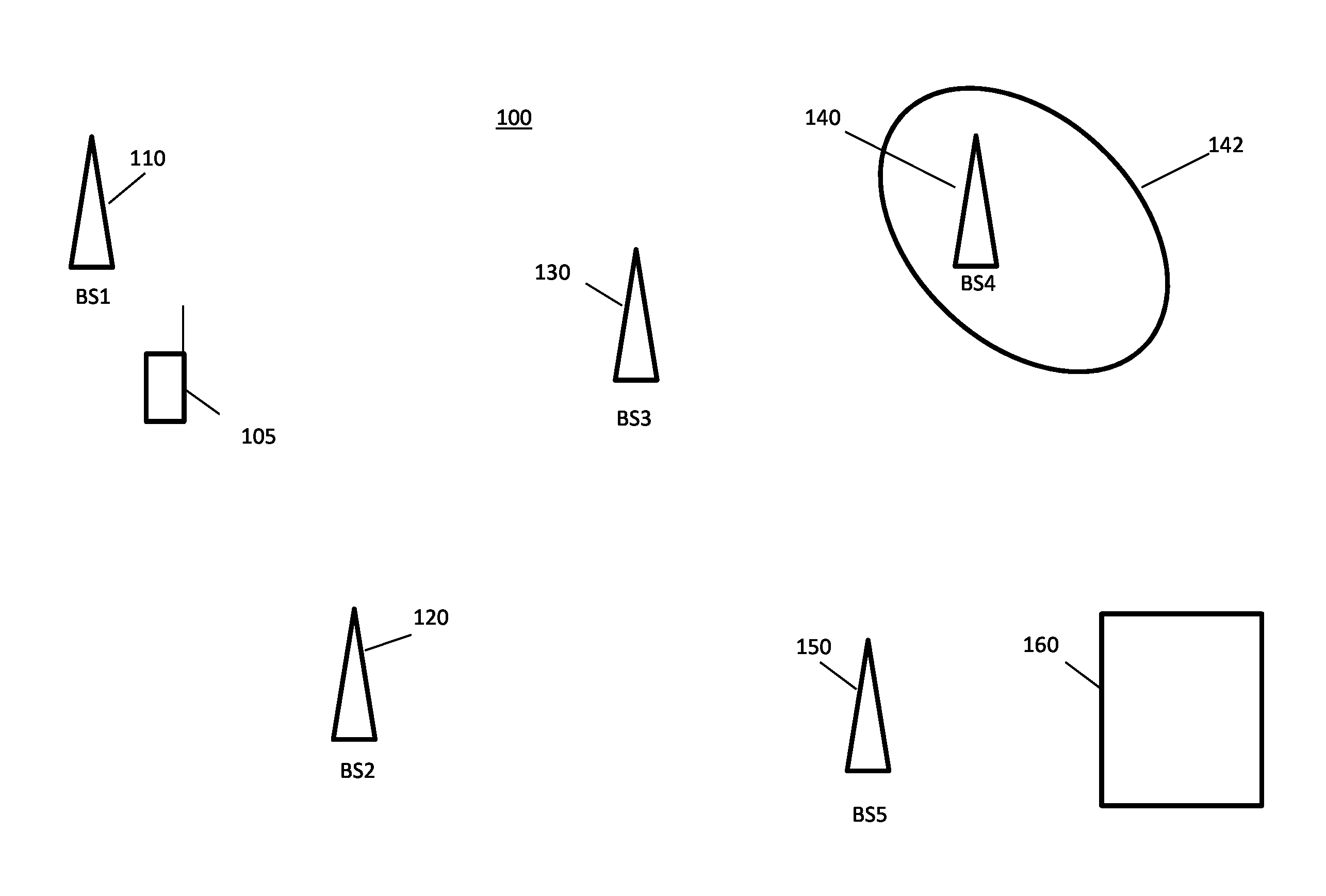
[0035]Before describing in detail embodiments that are in accordance with the present invention, it should be observed that the embodiments reside primarily in combinations of method steps and apparatus components related to a computer camera lighting system and method. Accordingly, the apparatus components and method steps have been represented where appropriate by conventional symbols in the drawings, showing only those specific details that are pertinent to understanding the embodiments of the present invention so as not to obscure the disclosure with details that will be readily apparent to those of ordinary skill in the art having the benefit of the description herein.

[0036]In this document, relational terms such as first and second, top and bottom, and the like may be used solely to distinguish one entity or action from another entity or action without necessarily requiring or implying any actual such relationship or order between such entities or actions. The terms “comprises...


PUM


Abstract

A method and apparatus for generating reference signatures for use in geolocation in a cellular wireless communication system is provided. A first signature for a mobile communication unit comprises location information, a timestamp, and radio frequency measurement information obtained by a mobile communication unit at a location, but does not contain identification information for the mobile communication unit. The first signature is compared to signatures in a database, to identify a second signature that has a timestamp and radio frequency measurement information that correspond to those of the first signature. A reference signature is created by combining at least a part of the first signature with at least a part of the second signature. Repetition of the comparison and combination steps creates a database of reference signatures, for use in geolocating other received call signatures.

Description

CROSS REFERENCE TO RELATED U.S. APPLICATIONS[0001]This application is related to copending U.S. patent application Ser. No. ______, entitled METHOD AND SYSTEM FOR MOBILE REFERENCE SIGNATURE GENERATION and having atty docket no. Arieso-24055 and also to co-pending U.S. patent application Ser. No. ______, entitled MOBILE COMMUNICATION SYSTEM and having atty docket no. Arieso-24060, both filed Dec. 18, 2012, and the disclosures of which are both incorporated herein by reference.FIELD OF THE INVENTION[0002]The field of the invention relates to a system and method for generating reference signatures in a mobile communication system.BACKGROUND OF THE INVENTION[0003]Wireless communication systems, such as GSM and the 3rd Generation (3G) of mobile telephone standards and technology, are well known. An example of 3G standards and technology is the Universal Mobile Telecommunications System (UMTS™), developed by the 3rd Generation Partnership Project (3GPP™) (www.3gpp.org).[0004]The 3rd and 4...

Claims


Application Information

Patent Timeline
IPC IPC(8): H04W4/02
CPCH04W56/001H04W64/00G01S5/02526H04W64/006
Inventor MURPHY, CHRISTOPHERFLNAGAN, MICHAEL JOSEPHKENINGTON, PETER
Owner VIAVI SOLUTIONS UK
Learn More