Eureka AIR delivers breakthrough ideas for toughest innovation challenges, trusted by R&D personnel around the world.

Seat with adjustable back profile

Active Publication Date: 2014-06-19
LIW CARE TECH
View PDF16 Cites 6 Cited by
  • Summary
  • Abstract
  • Description
  • Claims
  • Application Information

AI Technical Summary

Benefits of technology

The patent describes a seat that has a locking mechanism to adjust the tension between holders. The seat also has plates that increase the area of the back support portion. The technical effect of this invention is to improve the comfort and adjustability of the seat.

Problems solved by technology

Standard seats with non-adjustable back profiles which do not appropriately match the spinal profile of the seat occupant may result in spine aches or even spine deformations.
Moreover, such seats do not allow correction of spine deformations.
Each contour adjusting mechanism is adjustable independently by individual motor means controlled with a central controller, which makes the construction relatively complex and costly.
The profile of the back support is relatively complicated to adjust due to a large number of segments.

Method used


Image

  • Seat with adjustable back profile
  • Seat with adjustable back profile
  • Seat with adjustable back profile

Examples


first embodiment

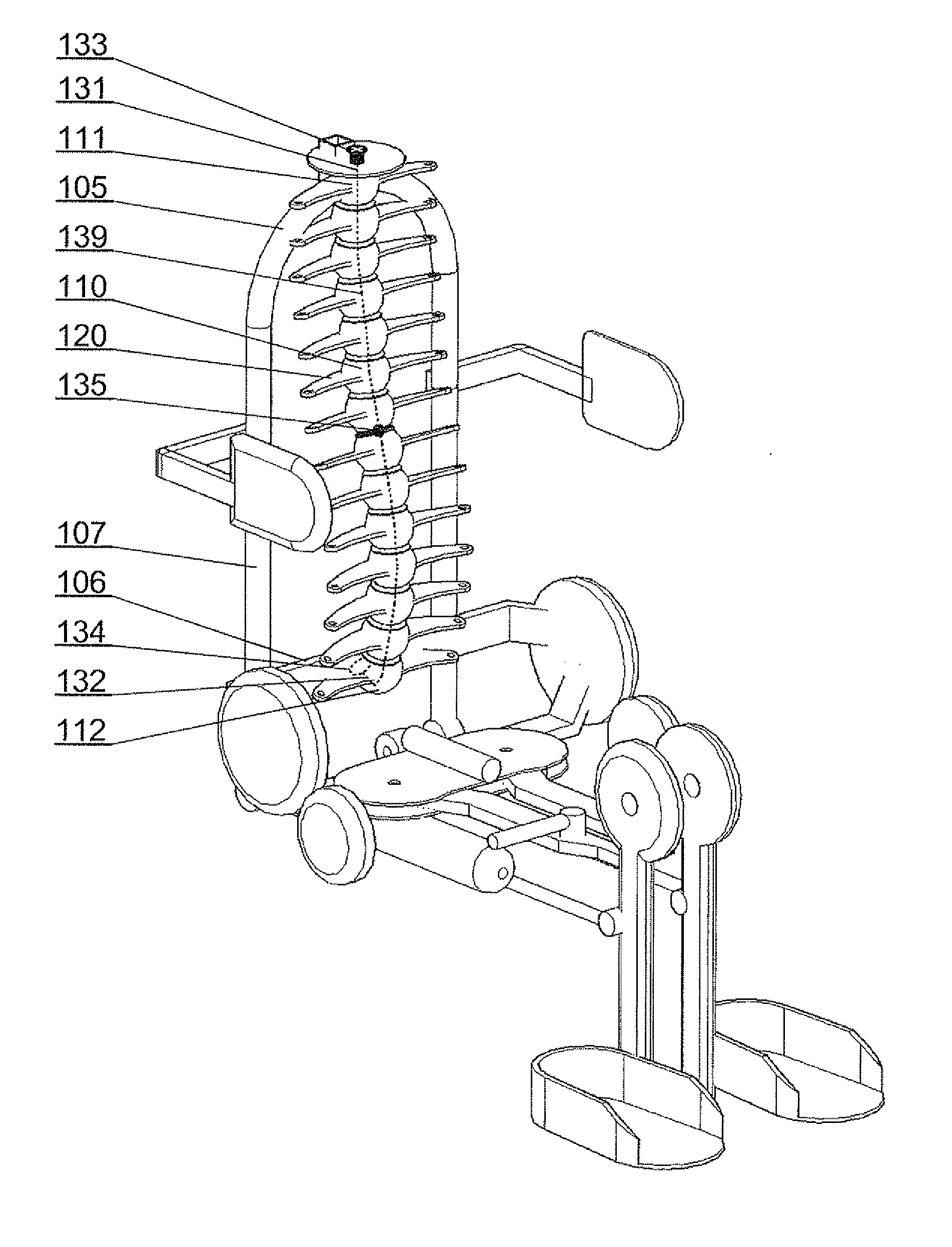
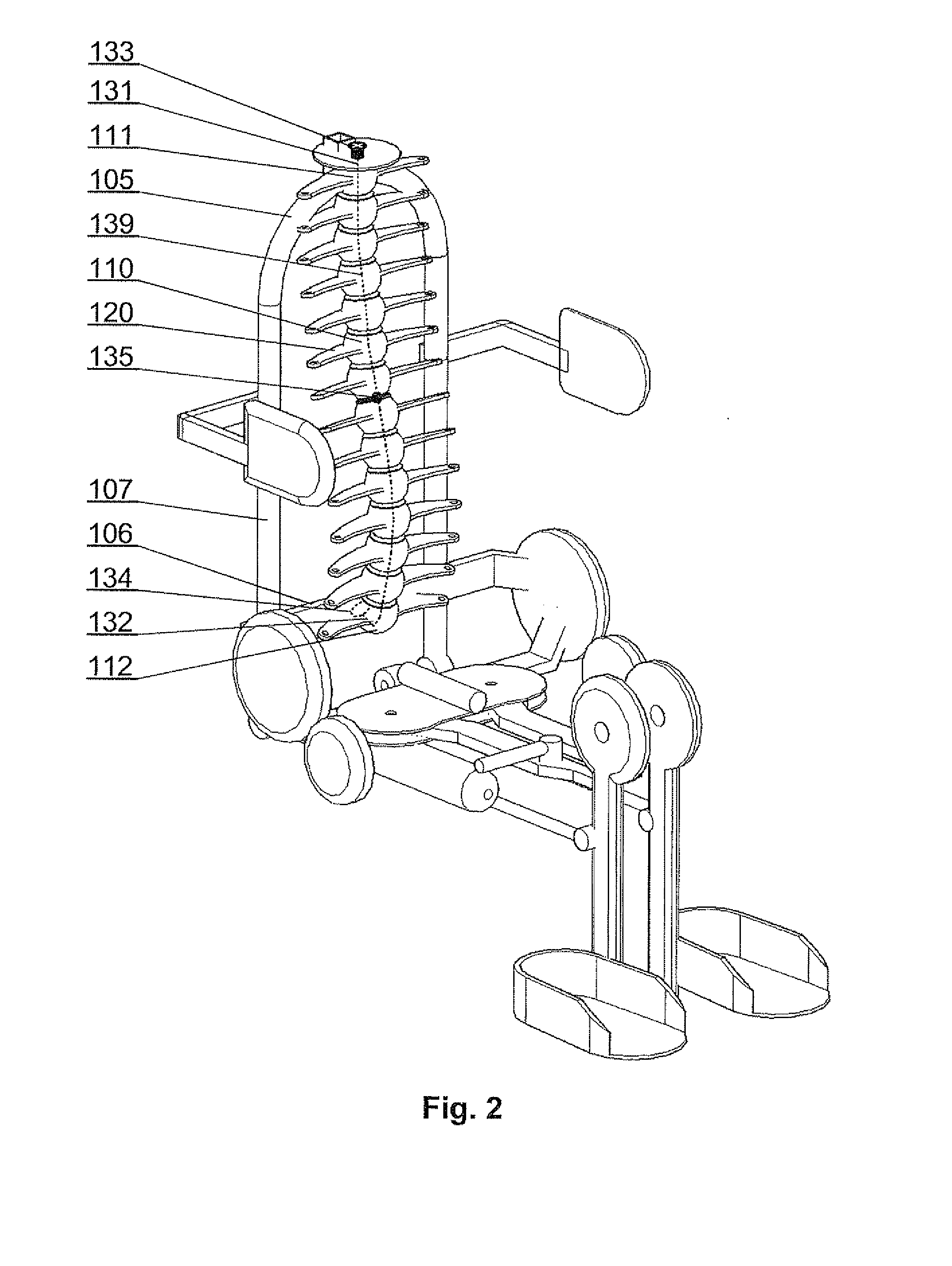
[0032]FIG. 2 shows a configuration of the seat with the back support portion according to the present invention. The adjustable core column 101 comprises a plurality of holders 110 and a plurality of side members 120 fixed to the holders 110. The side members 120 extend substantially in the width direction of the back support portion such as to profile its surface. Profile locking means 130, which in the present embodiment comprise an elastic element 139, preferably inextensible, such as a steel cord, a plastic cord or a chain, are coupled with a plurality of holders 110 and adjustable to an unlocked configuration, in which the holders 110 are individually rotatable around a plurality of axes such that the profile of the surface of the back support portion is adjustable and to a locked configuration, in which the holders 110 are fixed still with respect to each other and the profile of the surface of the back support portion is locked.

[0033]The profile locking means 130 in the prese...

second embodiment

[0036]FIG. 4 shows a configuration of the core column according to the present invention, and FIGS. 5 shows exploded view of its structural elements. The core column comprises holders 310 of tubular shape, to which side members 320 are fixed. A spacer 340, preferably in a form of a sphere, is placed between neighboring holders 310 and partially fits inside the tubular holders 310. The holders 310 have a coarse, preferably serrated, top and bottom edges 313, 314 configured to receive partially the spherical spacers 340 having a diameter larger than the internal diameter 316 of the tubular holders 310. The coarse edges 313, 314 of the holders 310 increase the friction between the spacers 340 and the holders 310 in the locked configuration of the core column, thereby fixing still the position of the holders 310 with respect to each other. The spacers 340 have a central through-hole 343 which is preferably narrower than the internal diameter of the holders 310 and preferably substantial...

third embodiment

[0037]FIG. 6 presents a configuration of the core column according to the invention, and FIGS. 7A and 7B present top and bottom views of the holders used in this embodiment. The core column comprises holders 410 with integrated side elements 420. A spacer 440 having a form of a cylinder with coarse surface is placed between the holders 410 and fits partially into the holders 410. The holders 410 have in their top portion a cylindrical recess 411, in which the spacer 440 can rotate around a horizontal axis, and in their bottom portion a triangular recess 412, in which the spacer 440 can rotate around a vertical axis. Therefore, in the unlocked configuration, the neighboring holders 410 can be rotated with respect to each other both around a horizontal and a vertical axis. The side elements 420 may have longitudinal openings 421 for mounting therein a plate for increasing the profiled back surface, in a range of widths corresponding t the width of the longitudinal opening 421.

[0038]Va...


PUM


Abstract

A seat comprising a back support portion (100) with adjustable surface profile, comprising an adjustable core colmnn (101) arrangedalong the height direction of the back support portion (100) and comprising a plurality of holders (110, 210, 211, 310, 410) and a plurality of side members (120, 220, 221, 320, 420) fixed to the holders (110, 210, 211, 310, 410) and extending substantially in the width direction of the back support portion (100) such as to profile the surface of the back support portion (I 00). It further comprises profile locking means (130) coupled with a plurality of holders (II 0, 210, 211, 310, 410) and adjustable to an unlocked configuration, in which the holders (110, 210, 211, 310, 410) are individually rotatable around a plurality of axes and the profile of the surface of the back support portion (100) is adjustable and to a locked configuration, in which the holders (II 0, 210, 211, 310, 410) are fixed still with respect to each other and the profile of the surface of the back support portion (100) is locked.

Description

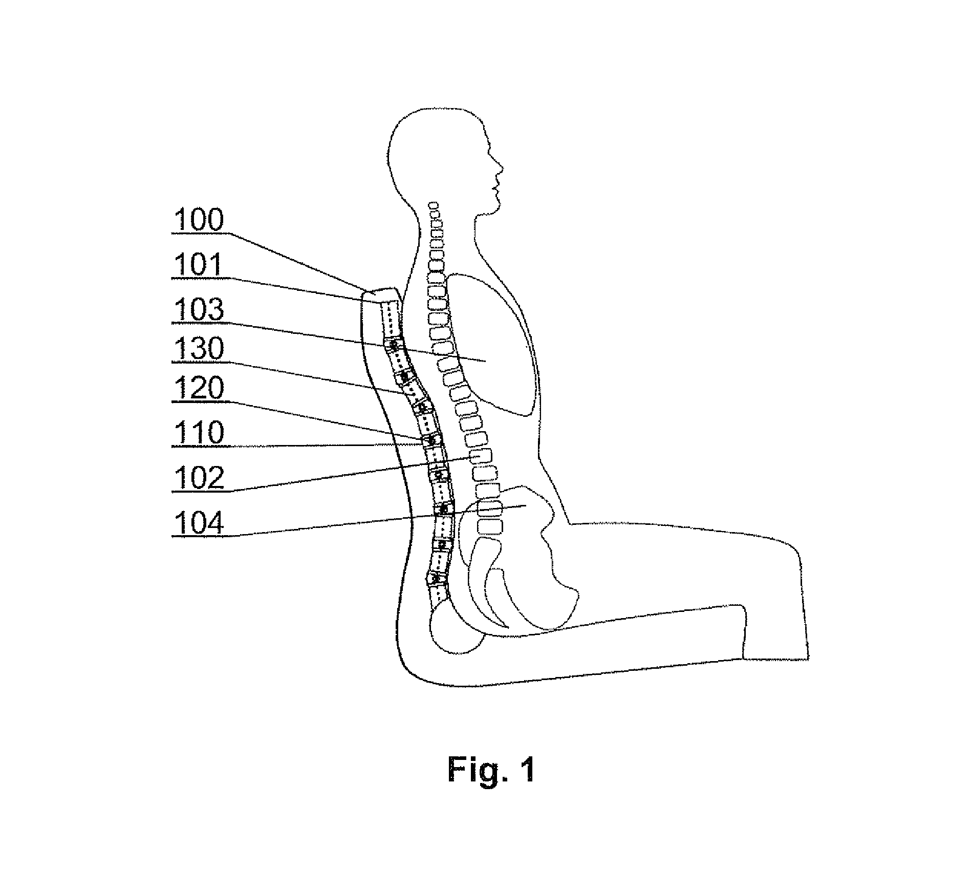
TECHNICAL FIELD[0001]The present invention relates to seats having back support portion with an adjustable surface profile.BACKGROUND ART[0002]The profile of the back support portion of a seat impacts not only the comfort of seating, but physiological functions of the organism as well. Standard seats with non-adjustable back profiles which do not appropriately match the spinal profile of the seat occupant may result in spine aches or even spine deformations. Moreover, such seats do not allow correction of spine deformations. Seats with adjustable back profile are known, which can be used to increase the comfort of seating or even help in correcting spine deformations of the occupant.[0003]A U.S. Pat. No. 4,944,554 presents an active biomechanical chair with a back rest comprising a plurality of contour adjusting mechanisms having plate means which are horizontally adjustable to fit with a spinal profile of a person using the chair. Each contour adjusting mechanism is adjustable inde...

Claims


Application Information

Patent Timeline
IPC IPC(8): A47C7/46
CPCA47C7/462A47C7/405A47C31/126A61G5/12A61G5/1091A61G5/122
Inventor KORDYL, GRZEGORZ
Owner LIW CARE TECH
Why Eureka
Eureka Blog
Learn More