
High contrast tire pattern

Inactive Publication Date: 2014-06-19
MICHELIN & CO CIE GEN DES ESTAB MICHELIN +1
View PDF4 Cites 10 Cited by
  • Summary
  • Abstract
  • Description
  • Claims
  • Application Information

AI Technical Summary

Benefits of technology

The tire and mold described in this patent result from the application of specific rules to create a pattern with high contrast. This design helps improve the time it takes to machine the mold, while still maintaining the quality of contrast between the pattern and the rest of the tire's surface, even from an observer's perspective.

Problems solved by technology

However, a pattern comprising such strands may be less resistant to certain mechanical attacks which the tire may sustain during its use.
The production of striations in a mold takes more time overall than the production of holes for molding strands.
Depending on the direction of the light rays returned by the residual surfaces and on the position of the observer relative to the tire, the pattern may then present differences of contrast with the rest of the sidewall of the tire and therefore in certain cases have inferior visibility.

Method used


Image

  • High contrast tire pattern
  • High contrast tire pattern
  • High contrast tire pattern

Examples


Embodiment Construction

[0043]In the following description, elements that are substantially identical or similar will be indicated by identical references.

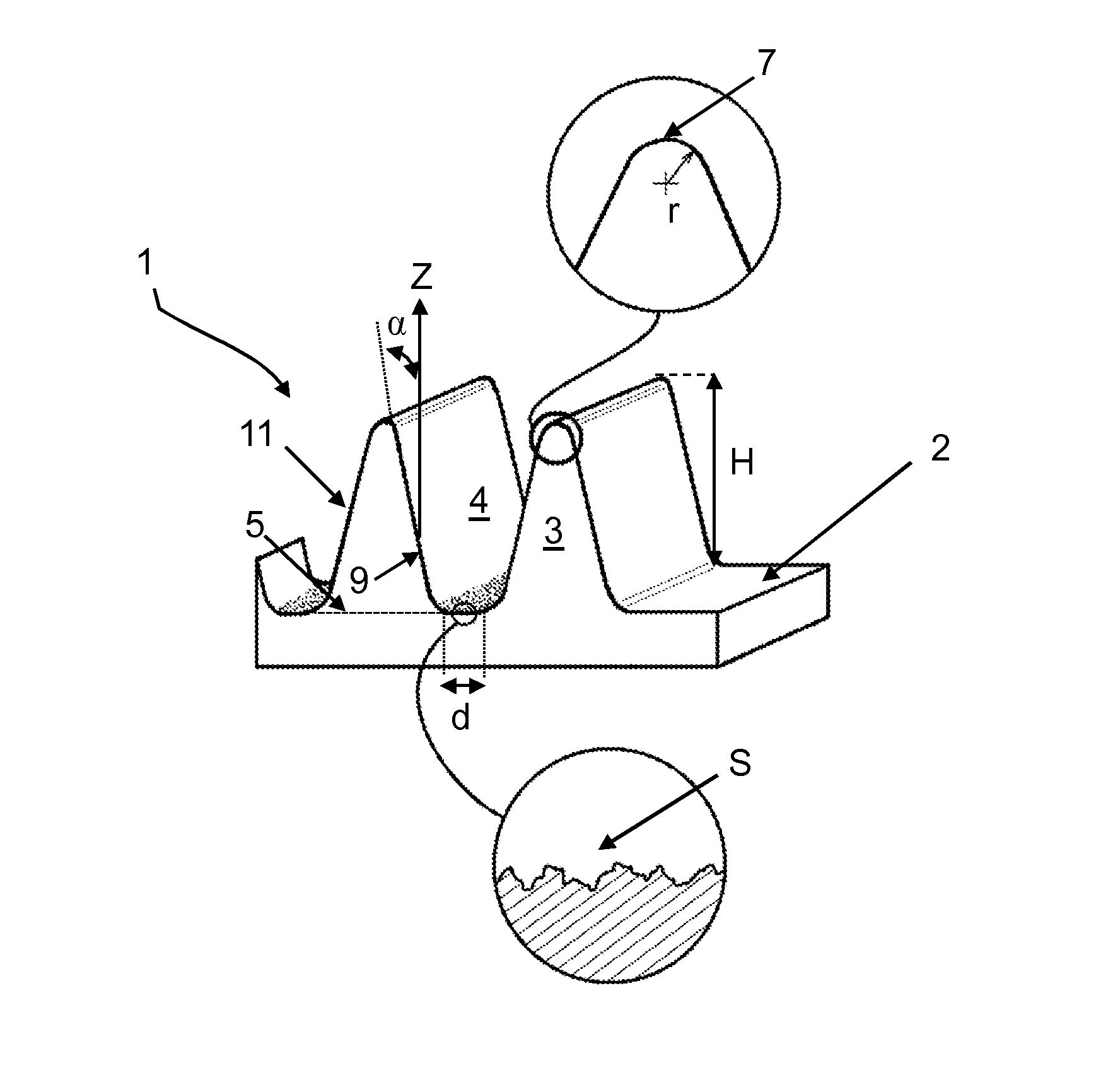
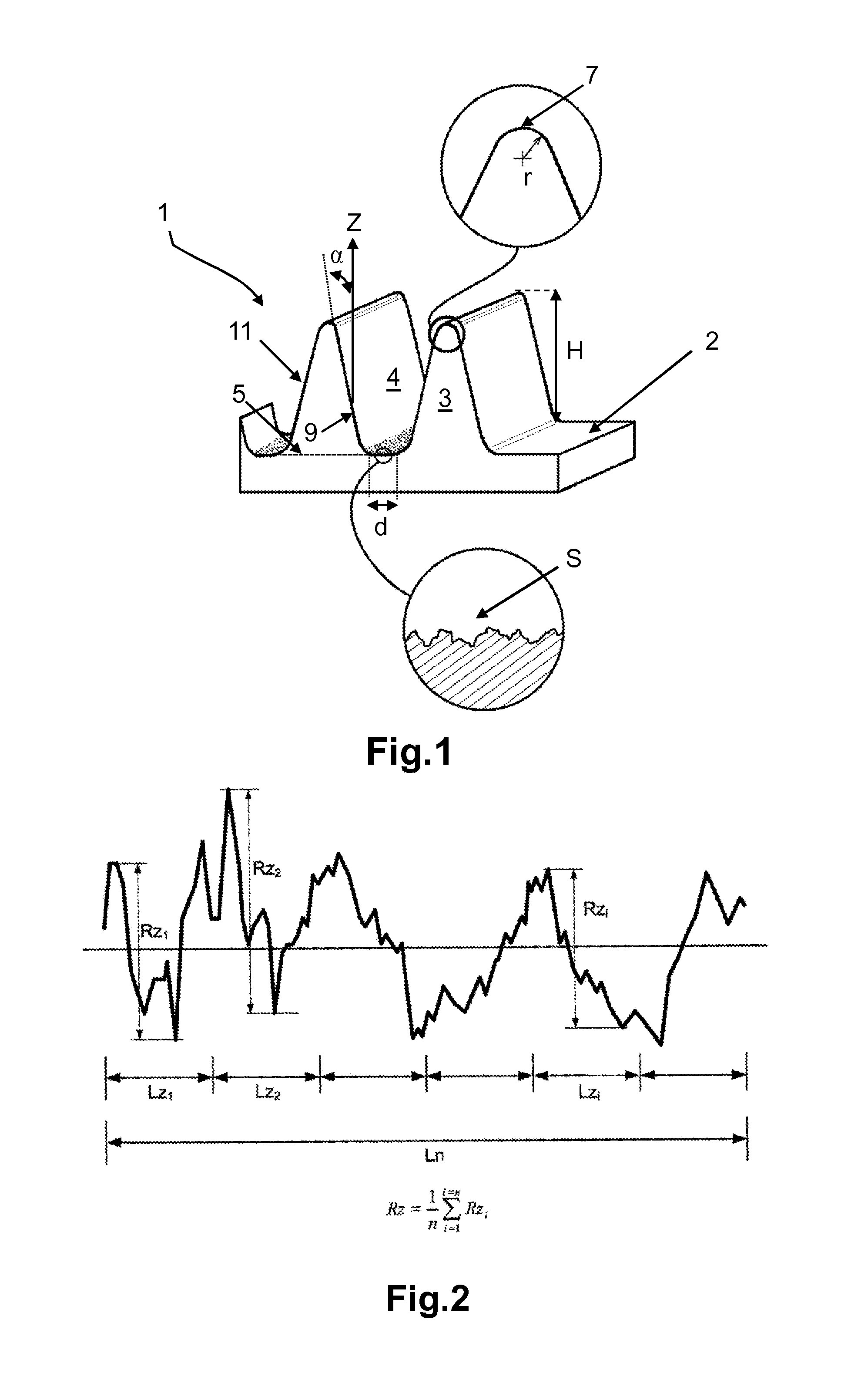
[0044]FIG. 1 represents schematically a view in perspective of a pattern 1 according to the invention.

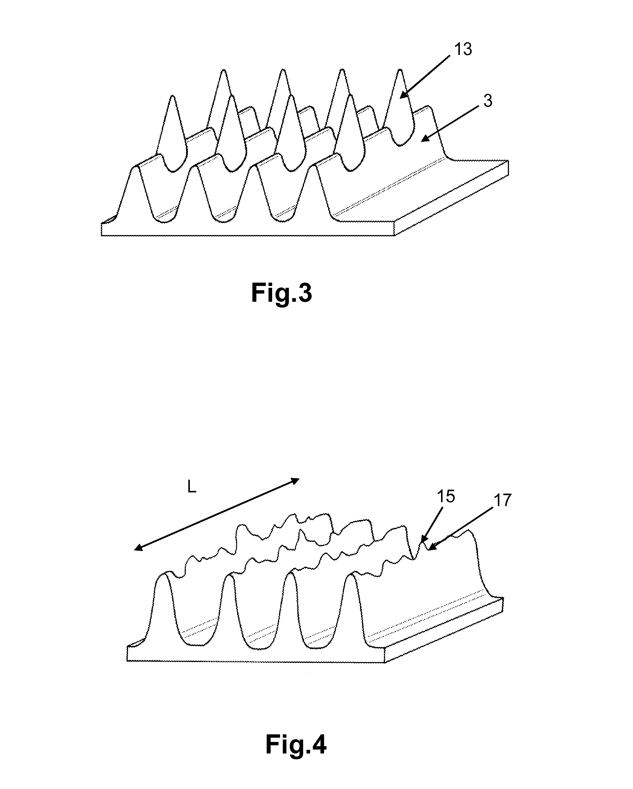
[0045]The pattern 1 comprises bars 3 separated by grooves 4.

[0046]Each bar may in this instance be divided into three layers: a tip layer, a base layer, and an intermediate layer placed between the tip layer and the base layer.

[0047]The tip layer is delimited by a curved surface with an average radius r of between 0.005 mm and 0.05 mm. The tip 7 of the bar corresponds to all of the highest points of the tip layer taken in the length of the bar.

[0048]The intermediate layer is delimited by two rectilinear inclined walls which extend in the length of the bar. The angle of inclination a of the inclined walls is in this instance less than or equal in absolute value to 25° relative to a direction Z perpendicular to the surface 2 of the tire comprising the patt...


PUM

PropertyMeasurementUnit
Lengthaaaaaaaaaa
Lengthaaaaaaaaaa
Angleaaaaaaaaaa

Abstract

A rubber tire comprising a surface having, over at least a portion of this surface, a pattern comprising a plurality of bars placed substantially parallel with one another, each comprising a tip distant from the surface of the tire and a base materially integral with the tire. Each bar of the plurality of bars comprises two inclined walls extending on either side of the tip towards the base, the angle of inclination of each inclined walls less than or equal in absolute value to 25° relative to a direction perpendicular to the surface. The bases of the bars are not in contact with one another so that the bases of two adjacent bars delimit a residual surface between the bars. The width of the residual surface corresponding to a distance between the bases of the two adjacent bars is less than or equal to half the height of the adjacent bars, the height being between 0.1 mm and 0.8 mm.

Description

BACKGROUND[0001]1. Field[0002]Disclosed herein is a tire for a motor vehicle comprising a pattern with high contrast and a mold for the molding and curing of the said tire.[0003]2. Description of The Related Art[0004]The sidewalls of tires have a large quantity of patterns, also called markings. These patterns are designed on the one hand to give technical and legal information and on the other hand to allow consumers to identify the origin of the product.[0005]There are constant attempts to improve the visibility and legibility of these patterns on the sidewalls of the tires.[0006]Document WO2007 / 045425 describes a pattern with high contrast comprising a plurality of strands protruding from a tire surface. “Strand” means a filiform element of which the height is at least equal to twice the diameter of a disk with the same surface area as the average section of the strand.[0007]The effect of these strands is to “trap” the incident light rays which meet the surface of the pattern. Th...

Claims


Application Information

Patent Timeline
IPC IPC(8): B60C13/00B29D30/72
CPCB29D30/72B60C13/001
Inventor MUHLHOFF, OLIVIERPATURLE, ANTOINEDESVIGNES, JEAN-CLAUDE
Owner MICHELIN & CO CIE GEN DES ESTAB MICHELIN
Learn More