
Pouch for collecting liquid excretions

a technology for excretions and pouches, applied in the field of pouches for collecting liquid excretions, can solve the problems of limiting the useful volume of pouches, and achieve the effects of wide mutual distance, restricted bulking out, and discomfort for users

Active Publication Date: 2014-06-12
HOLLISTER INCORPORAED
View PDF23 Cites 9 Cited by
  • Summary
  • Abstract
  • Description
  • Claims
  • Application Information

AI Technical Summary

Benefits of technology

This patent describes a pouch for collecting liquid excretions from the human body with an anti-reflux arrangement. The pouch has an arcuate seal and slits that allow for increased active volume and allow for fluid to flow through even when the pouch is inclined. The pouch also has a baffle member to prevent sloshing and bulking out, while attachment lines are tapered to reduce strains and stresses on the pouch's walls. Additionally, a non-woven comfort layer is provided on the outer side of the pouch for increased comfort and reduced noise during use.

Problems solved by technology

The anti-reflux valve arrangement in the pouch takes up a certain volume inside and thereby limits useful volume of the pouch.

Method used


Image

  • Pouch for collecting liquid excretions
  • Pouch for collecting liquid excretions
  • Pouch for collecting liquid excretions

Examples


first embodiment

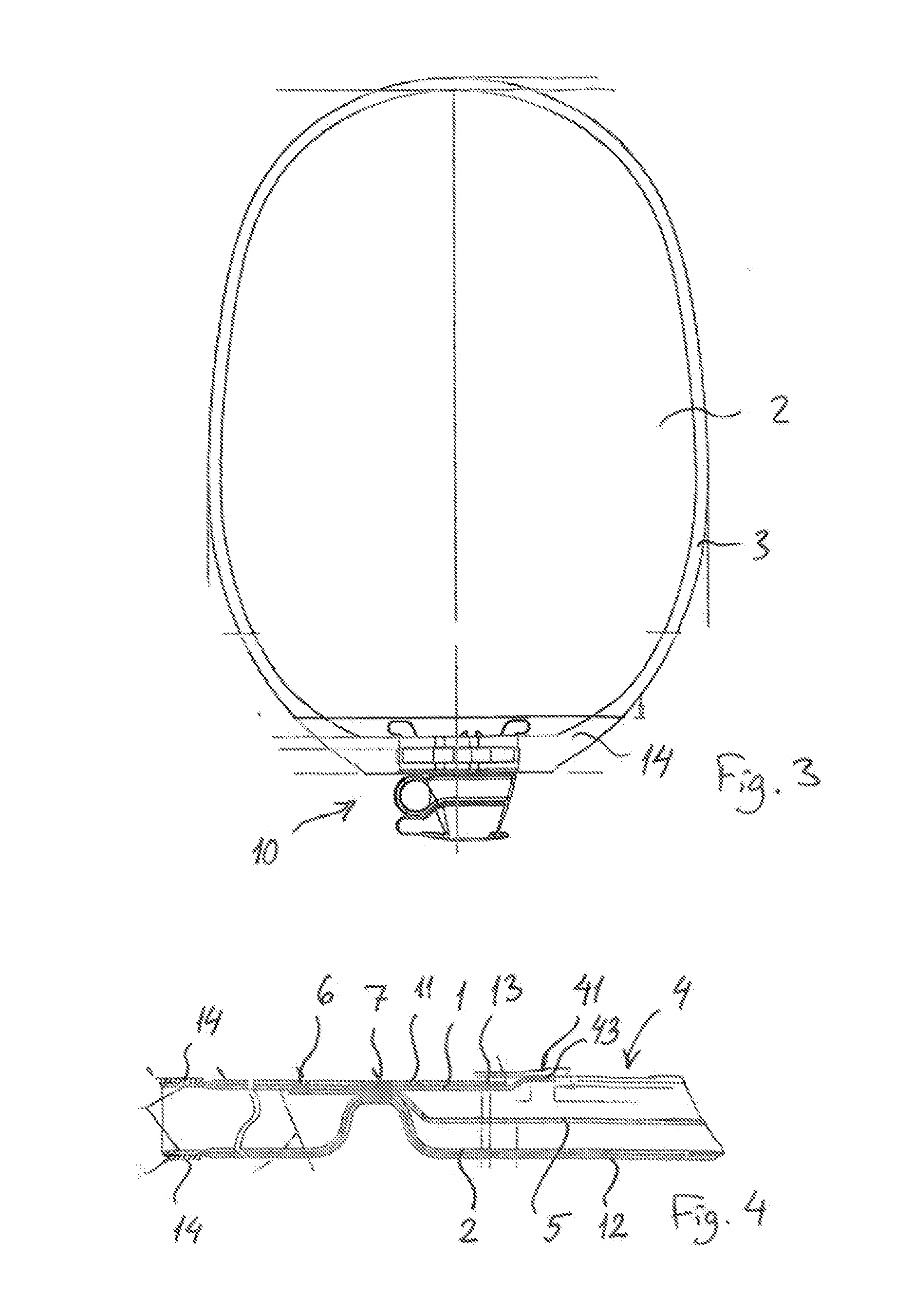
[0022]With reference to FIGS. 1 to 4, a pouch for collecting liquid excretions according to the disclosure is shown, The pouch comprises a body-side first wall 1 and a distal second wall 2 which are sealed along their periphery 3 to form the pouch. In the top section 20 of the pouch, an inlet opening 4 is provided in the first wall 1. An intermediate anti-reflux film 5 is provided in the top section 20 between the first and second walls 1, 2, The anti-reflux film 5 may be sealed to the first wall 1 at its lower periphery 6 and to the first and second walls 1, 2 at their common periphery. The anti-reflux film 5 covers the opening 4 and the lower seal 6 is provided a certain distance from the opening 4. The lower seal 6 is preferably provided substantially concentric with the inlet opening 4, i.e. the seal 6 expands across the pouch with a concave shape. A number of adhesion areas, such as spot welds 7, are provided in a similar concave arcuate configuration across the pouch and prefe...

second embodiment

[0028]With reference to FIGS. 5 and 6 a pouch according to the disclosure is shown, The pouch is similar in its design as in the previously described embodiment, i.e. with a body-side first wall and a distal second wall 2 which are sealed along their periphery 3 to form the pouch. In the top section of the pouch, an inlet opening 4 is provided in the first wall 1. An intermediate anti-reflux film 5 may be provided in the top section between the first and second walls 1, 2, The anti-reflux film 5 may be sealed to the first wall 1 at its lower periphery 6 and to the first and second walls 1, 2 at their common periphery. The anti-reflux film 5 covers the opening 4 and the lower seal 6 is provided a certain distance from the opening 4, The lower seal 6 is preferably provided substantially concentric with the inlet opening 4, i.e. the seal 6 expands across the pouch with a concave shape. A number of spot welds 7 are provided in a similar concave arcuate configuration across the pouch and...


PUM

PropertyMeasurementUnit
melting pointaaaaaaaaaa
adhesionaaaaaaaaaa

Abstract

The present invention concerns a pouch for collecting liquid excretions for collecting human waste, said pouch comprising a first and second wall sealed together along their periphery defining an inlet top portion and a bottom portion defining a collection chamber, an inlet opening provided in the top portion of the first wall, and an anti-reflux film provided in the top portion between said first and second walls, wherein the anti-reflux film is sealed along its lower periphery to the first wall by an anti-reflux seal across the first wall, and wherein a plurality of spot welds are provided above the anti-reflux seal and wherein a plurality of slits are provided in the anti-reflux film between the anti-reflux seal and the spot welds.

Description

BACKGROUND[0001]The present invention relates to a pouch for collecting liquid excretions, such as, for example, a urostomy pouch for collecting liquid human waste, said pouch comprising a first and second wall sealed together along their periphery defining an inlet top portion and a bottom portion defining a collection chamber, an inlet opening provided in the top portion of the first wall, and an anti-reflux film provided in the top portion between said first and second walls,[0002]In order to avoid content from refluxing once it has entered the pouch it is well known to provide a non-return valve in the vicinity of the inlet opening through which urine exits the stoma and enters into the pouch, An example of such arrangement is known from EP 749 507 A2.[0003]Other examples of non-return valve arrangements in urine collection pouches are known from U.S. Pat. No. 4,604,095 and U.S. Pat. No. 4,300,560.[0004]The non-return valve arrangement comprises the provision of intermediate fil...

Claims


Application Information

Patent Timeline
Patent Type & Authority Applications(United States)
IPC IPC(8): A61F5/443
CPCA61F5/443A61F5/4405A61F5/4407A61F5/445Y10T156/10
Inventor HANNAN, JOHN FRANCISRASMUSSEN, CLAUS DALLERUPGOCZKOWSKI, JAKUB ZYGMUNT
Owner HOLLISTER INCORPORAED
Learn More