
Luminaire with switch-mode converter power monitoring

a technology of power monitoring and switch-mode converters, which is applied in the direction of discharge tube/lamp details, electric discharge lamps, discharge tube/lamp details, etc., can solve problems such as power consumption of converters, and achieve the effect of improving power measurement in devices

Active Publication Date: 2014-06-12
EXPRESS IMAGING SYST
View PDF5 Cites 45 Cited by
  • Summary
  • Abstract
  • Description
  • Claims
  • Application Information

AI Technical Summary

Benefits of technology

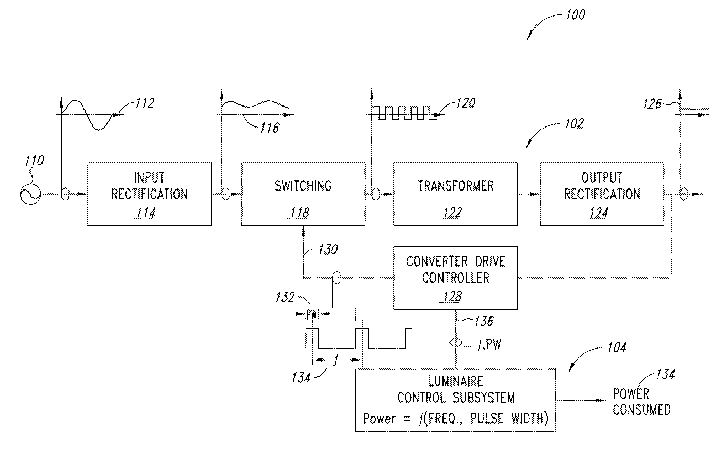
The patent text describes a power monitoring system for a switch-mode power converter. The system includes a power converter drive circuit and a control subsystem. The control subsystem analyzes information about the converter drive circuit, such as the frequency or pulse width of the signal, to determine the power output of the converter. This relationship is used to calculate the power consumed by the load. The system can also include sensors to measure environmental conditions and adjust the power output accordingly. The technical effect of this system is to provide a more accurate measure of power consumption and facilitate the optimization of power conversion efficiency.

Problems solved by technology

A resonant switch mode converter such as an LLC type converter alters the frequency of a constant duty cycle (e.g., an approximately 50% duty cycle) drive signal to adjust the output voltage or current and thereby the power consumption of the converter.

Method used


Image

  • Luminaire with switch-mode converter power monitoring
  • Luminaire with switch-mode converter power monitoring
  • Luminaire with switch-mode converter power monitoring

Examples


Embodiment Construction

[0041]In the following description, certain specific details are set forth in order to provide a thorough understanding of various disclosed embodiments. However, one skilled in the relevant art will recognize that embodiments may be practiced without one or more of these specific details, or with other methods, components, materials, etc. In other instances, well-known or well-documented electrical or electronic components such as full wave and half wave rectifiers, semiconductor switching devices, and filtering circuits and structures associated with luminaires, timing circuits, real time clock circuits, data look-up tables, and the like have not been shown or described in detail to avoid unnecessarily obscuring descriptions of the embodiments.

[0042]Unless the context requires otherwise, throughout the specification and claims which follow, the word “comprise” and variations thereof, such as “comprises” and “comprising,” are to be construed in an open, inclusive sense that is as “...


PUM


Abstract

The power consumption of a switch-mode power converter can be determined based upon at least one of a converter drive signal pulse width or a converter drive signal frequency. Such power consumption can be determined using an algorithm providing a functional relationship between switch-mode power converter power consumption and at least converter drive signal pulse width or frequency. Such algorithms can be either calculated using known component values or empirically determined. Such power consumption may also be determined using store power consumption data in a data store that is indexed by at least one of the converter drive signal pulse width or frequency.

Description

BACKGROUND[0001]1. Technical Field[0002]The present disclosure generally relates to the field of illumination devices and, more particularly, to power monitoring of illumination devices using switch-mode power converters.[0003]2. Description of the Related Art[0004]Power measurement has traditionally relied upon measuring the current and voltage supplied to a load. Typical voltage measurement involves the use of an analog to digital converter. Typical current measurement involves the measurement of the voltage across a current sense resistor, or current sensing transformer, using an analog to digital converter. Because the alternating current used in many municipal, commercial, and industrial lighting systems is not supplied as a perfect sinusoid, the calculation of power is not as straightforward as a simple multiplication of the voltage and current. In practice, a digital signal processor is often employed due to the need for high speed data acquisition, noise filtering, root-mean...

Claims


Application Information

Patent Timeline
IPC IPC(8): H05B33/08H05B44/00H05B45/50
CPCH05B45/50Y02B20/30H05B45/375H05B45/3725H05B45/385H05B47/20
Inventor REED, WILLIAM G.
Owner EXPRESS IMAGING SYST
Learn More