Cable connector and cable assembly, and method of manufacturing cable assembly
- Summary
- Abstract
- Description
- Claims
- Application Information
AI Technical Summary
Benefits of technology
Problems solved by technology
Method used
Image
Examples
first embodiment
[0044]Hereinafter, the present invention will be described in detail with reference to the drawings.
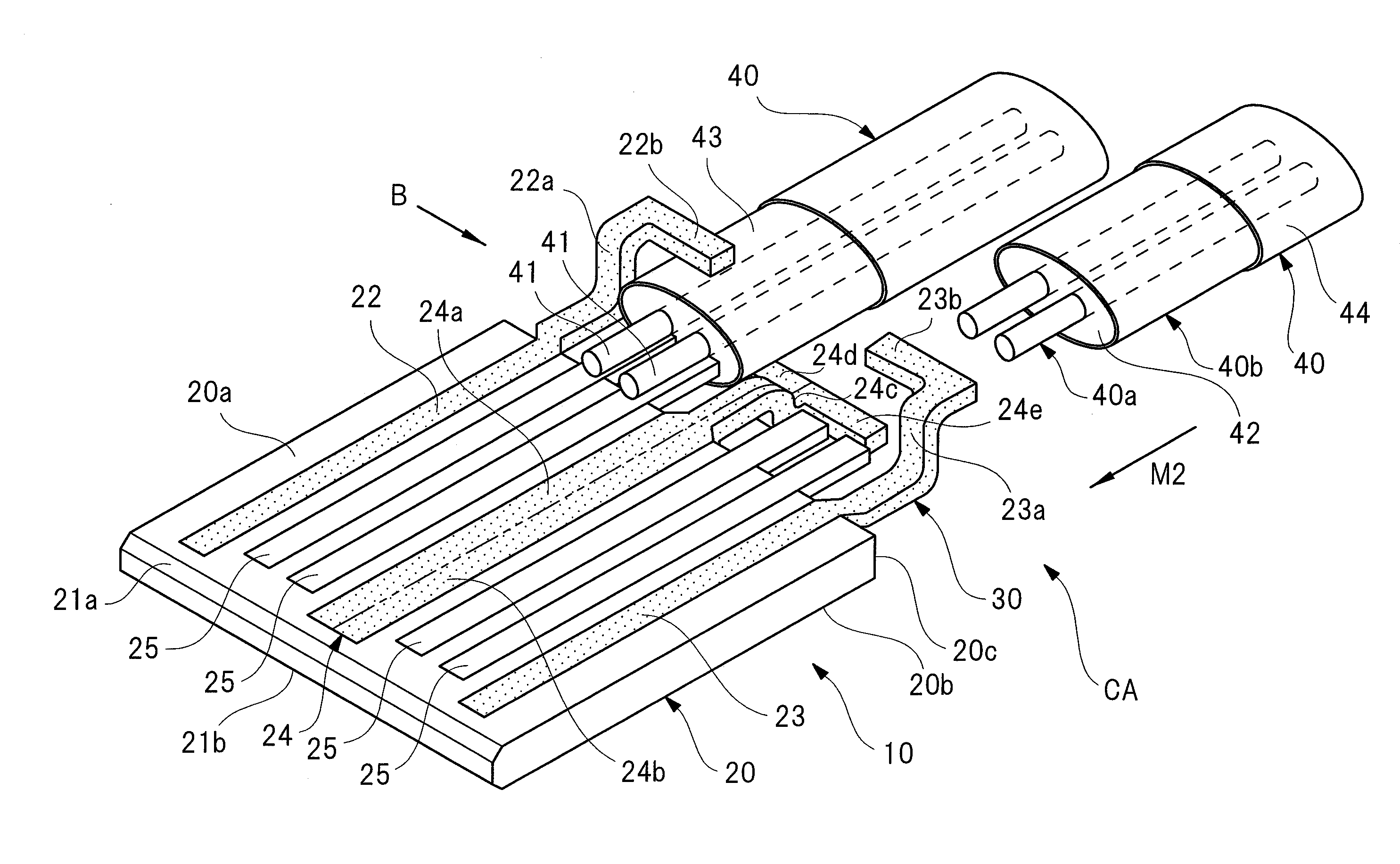
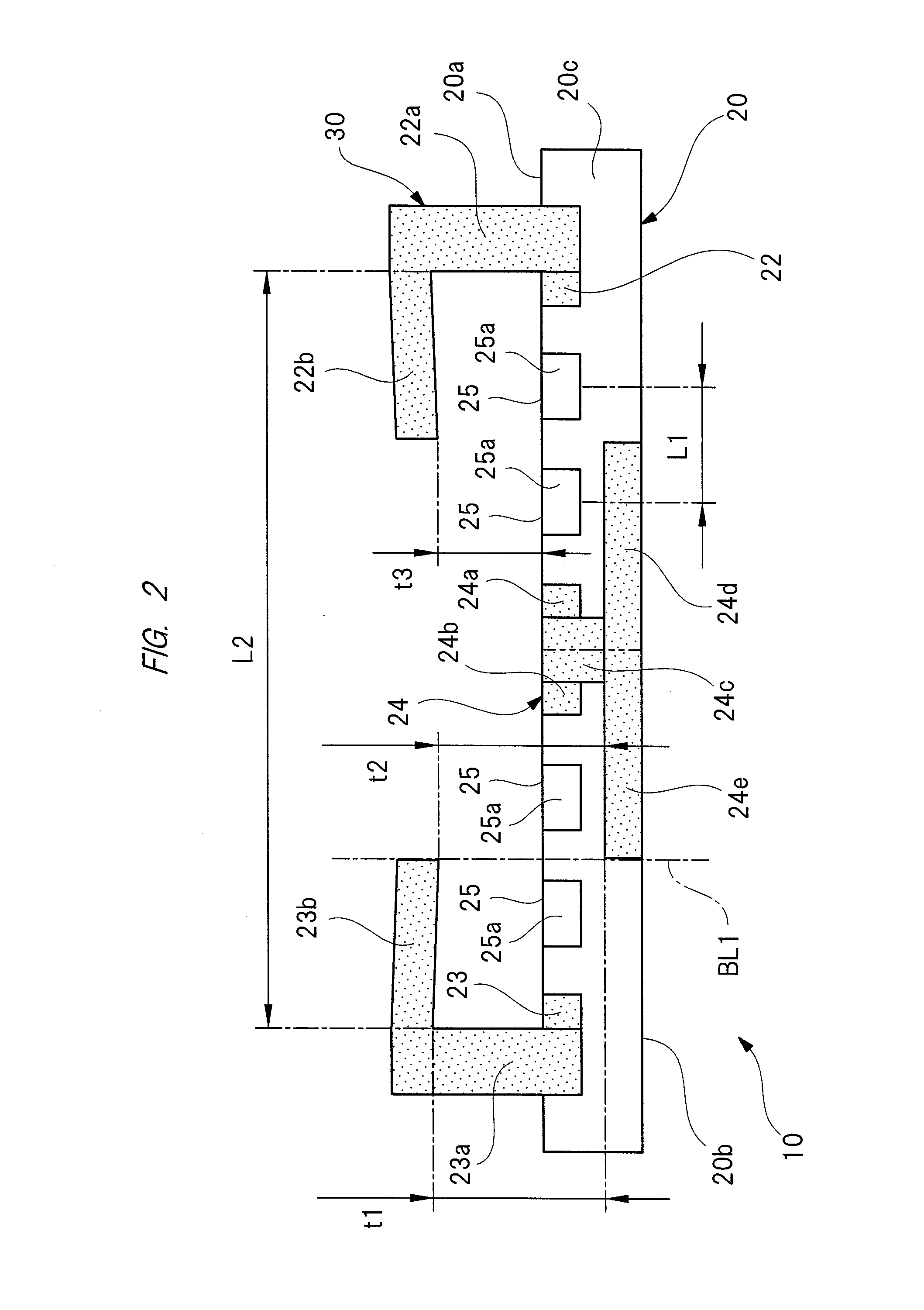
[0045]FIG. 1 is a perspective view illustrating a cable connector according to the first embodiment, FIG. 2 is a side view on an arrow “A” in FIG. 1, FIG. 3A is a perspective view of a cable for differential signal transmission, FIG. 3B is a cross-sectional view of the cable for differential signal transmission, FIGS. 4A and 4B are partially-enlarged views for explaining a manufacturing procedure (assembling procedure) of a cable assembly, FIG. 5 is a perspective view for explaining the manufacturing procedure of the cable assembly, and FIG. 6 is a side view on an arrow “B” in FIG. 5.
[0046]As illustrated in FIGS. 1 and 2, a cable connector 10 is provided with a connector main body (connector board) 20 and a cable connection portion 30. The connector main body 20 is configured to be inserted into, for example, a slot (socket) provided in a backplane product (not illustrated), and a plu...
third embodiment
[0105]FIG. 9 is a perspective view illustrating a cable connector according to the
[0106]As illustrated in FIG. 9, a cable connector 60 according to the third embodiment is different from the cable connector 10 according to the first embodiment (see FIG. 1) in only that holding reinforcement portions 61 to 64 extending in the longitudinal direction of the cable for differential signal transmission 40 are integrally provided with the front-side arm portions 22b and 23b and the rear-side arm portions 24d and 24e integrally provided with the respective ground contacts 22 to 24.
[0107]Here, since the respective holding reinforcement portions 61 to 64 are integrally provided with the front-side arm portions 22b and 23b and the rear-side arm portions 24d and 24e, they are arranged on the center portion CE of the cable for differential signal transmission 40 (see FIG. 4B).
[0108]Even in the cable connector 60 according to the third embodiment formed as described above, the same function effec...
fourth embodiment
[0110]FIG. 10 is a perspective view illustrating a cable connector according to the
[0111]As illustrated in FIG. 10, a cable connector 70 according to the fourth embodiment is different from the cable connector 10 according to the first embodiment (see FIG. 1) in only that two cable connectors 10 according to the first embodiment are arranged integrally with each other on boundary of a broken line “P” so as to provide slots SL1 to SL4. In this manner, four cables for differential signal transmission 40 are electrically connectable so as to correspond to the respective slots SL1 to SL4. However, the number of cable connectors 10 to be connected is not limited to two but is any number, and three or more cable connectors 10 may be arranged integrally with each other.
[0112]Even in the cable connector 70 according to the fourth embodiment formed as described above, the same function effect as that of the above-described first embodiment can be achieved.
[0113]Next, a fifth embodiment of th...
PUM
| Property | Measurement | Unit |
|---|---|---|
| Length | aaaaa | aaaaa |
| Thickness | aaaaa | aaaaa |
| Force | aaaaa | aaaaa |
Abstract
Description
Claims
Application Information
 - R&D
- Intellectual Property
- Life Sciences
- Materials
- Tech Scout
- Unparalleled Data Quality
- Higher Quality Content
- 60% Fewer Hallucinations
Browse by: Latest US Patents, China's latest patents, Technical Efficacy Thesaurus, Application Domain, Technology Topic, Popular Technical Reports.
© 2025 PatSnap. All rights reserved.Legal|Privacy policy|Modern Slavery Act Transparency Statement|Sitemap|About US| Contact US: help@patsnap.com


