Portable long-distance s.o.s. signaling device

a signaling device and long-distance technology, applied in the field of signaling devices, can solve the problems of only lasting a relatively short amount of time for flare illumination, and achieve the effects of facilitating other people's visibility, and reducing the distance between the signaling device and the targ

Inactive Publication Date: 2014-06-05
R&R LED DISTRESS SIGNALS INC SIGNAUX DE DETRESSE R&R LED INC
View PDF8 Cites 7 Cited by
  • Summary
  • Abstract
  • Description
  • Claims
  • Application Information

AI Technical Summary

Benefits of technology

The invention is a device that alerts other drivers on the road that there is a disabled car in their path, reducing motor vehicle collisions. The device includes powerful magnets that can easily be attached to a vehicle's metal roof or door, and is much brighter and clearer than other visual distress alert devices. The device is durable, waterproof, and can be stored when not in use. The raised letters on the device's housing make them even more visible from a distance. The device can also be powered by batteries for extended use.

Problems solved by technology

Moreover, these conventional signaling devices are typically only visible for a short distance away from the disabled vehicle, and the illumination of flares typically lasts for only a relatively short amount of time.

Method used


Image

  • Portable long-distance s.o.s. signaling device
  • Portable long-distance s.o.s. signaling device
  • Portable long-distance s.o.s. signaling device

Examples


first embodiment

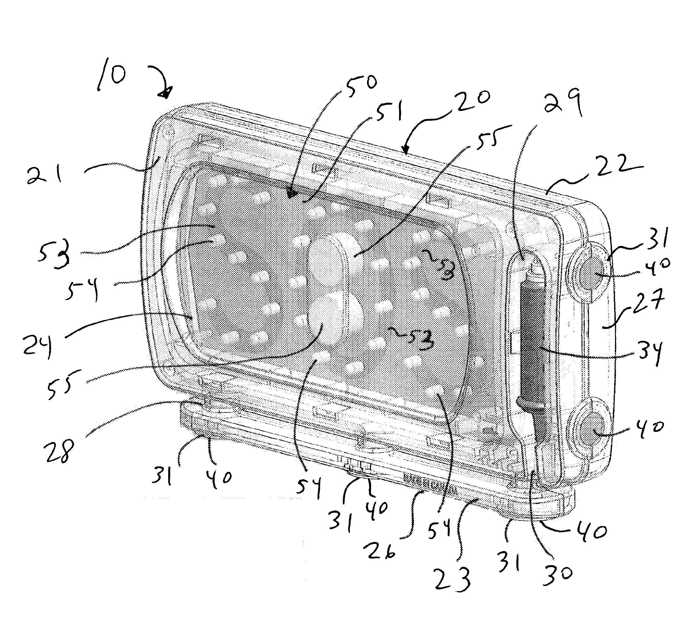
[0028]the present portable long distance S.O.S. signaling device 10 is shown in FIG. 1 as comprising housing 20, preferably constructed of a sturdy polycarbonate material and having front housing portion 21 and rear housing portion 22, which collectively form the overall housing. Housing 20 further includes base region 23, front lens region 24, back lens region 25 (shown in FIG. 3), bottom side 26, right side 27, power plug receptacle 29 communicating through channel 30 with cord reel region 28, and a plurality of magnet receptacles 31. Specifically, base region 23 includes three magnet receptacles 31 disposed on bottom side 26, spaced substantially equidistantly apart along the length of housing 20. Right side 27 includes two additional magnet receptacles, spaced proximate the top and bottom edges of housing 20. Each magnet receptacle 31 is substantially cylindrical in shape and securely retains a relatively powerful, substantially disc-shaped magnet 40, exposing a top outer surfac...

second embodiment

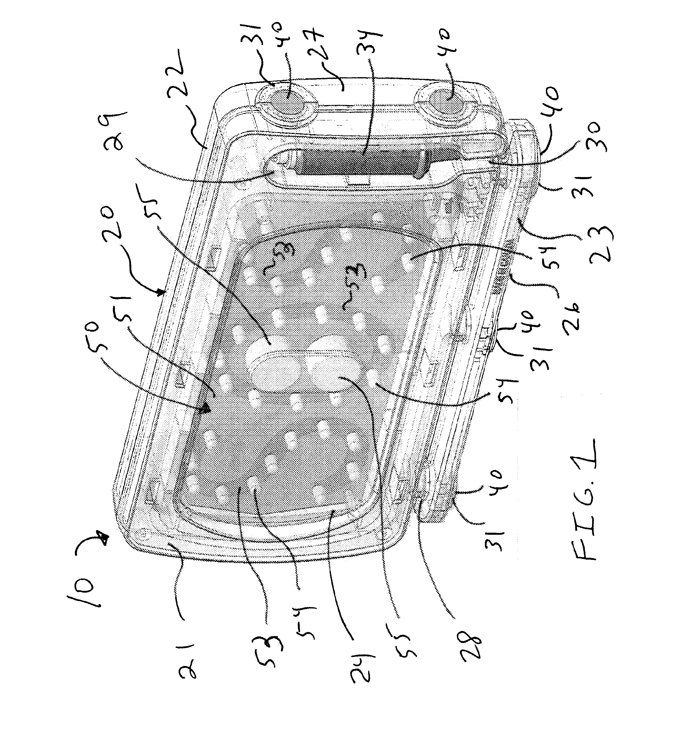
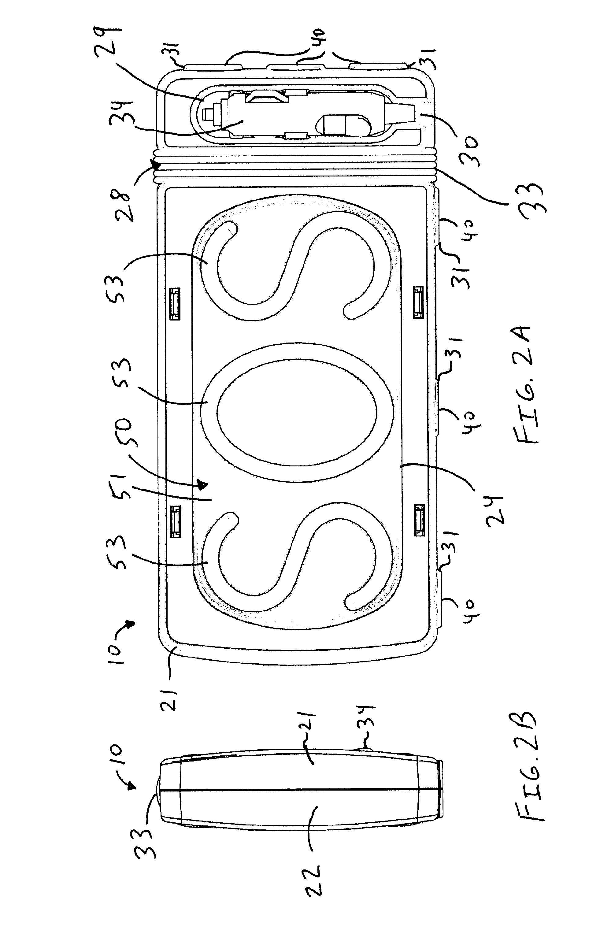
[0032]present portable long distance S.O.S. signaling device 10 is shown in FIGS. 2A, 2B, 3 and 4 (with LEDs 54 and 55 of display unit 50 being omitted in FIGS. 2A and 2B for clarity). In this embodiment, cord reel region 28 is disposed vertically, between power plug receptacle 29 and lens regions 24 and 25 of housing 20, rather than horizontally, along base region 23 of housing 20, as in the embodiment of FIG. 1. This, in turn, permits power cord 33 to be wound about cord reel region 28 in a vertical orientation, as opposed to a horizontal orientation, as in the embodiment of FIG. 1.

[0033]As shown in FIG. 3, in the event of a vehicle malfunction or other emergency situation, a driver of automobile 60 quickly and easily activate and deploy portable long distance S.O.S. signaling device 10 without leaving the safety of the vehicle's interior. In particular, once the unit 10 is retrieved from the glove compartment or other place of storage, power plug 34 is removed from power plug rec...


PUM


Abstract

A portable distress light signal device generates a visual S.O.S. distress signal indication visible from a significant distance away. Indicia including the letters “SOS” are disposed on either side of the device. A first set of light emitting diodes (LEDs) are disposed on both sides of the unit, each positioned within the interior of the region defined by each letter of the “SOS” indicia. A second set of LEDs, preferably of substantial power and luminosity, is likewise disposed on both sides of the unit, within the interior of the “O” portion of the “SOS” indicia. A power cord and power plug couples the unit to a source of electrical power, such as the cigarette lighter socket or 12-Volt accessory socket of an automobile or other vehicle. Powerful permanent magnets are preferably disposed about at least the bottom and right side edges of the housing, permitting the driver of an automobile to rapidly secure the unit to a ferromagnetic surface of the vehicle, such as the driver-side door or roof, in both cases with the SOS indicia oriented in horizontal orientation for easy recognition by passersby. Hazard warning stripes are disposed about the front and back sides of the housing for further enhanced visibility. Upon the application of power to the unit, an internal microcontroller repeatedly switches power to both the first and second sets of LEDs on and off causing them to pulse in a repeated sequence that corresponds to the S.O.S. signal in international Morse code.

Description

CROSS-REFERENCE TO RELATED APPLICATION[0001]This application claims the benefit of U.S. Provisional Patent Application No. 61 / 524,716, filed Aug. 17, 2011, the entirety of which is hereby incorporated by reference.BACKGROUND OF THE INVENTION[0002]1. Field of the Invention[0003]The present invention relates, in general, to signaling devices and, more particularly, to a portable distress light signal device.[0004]2. General Background of the Invention[0005]Emergency signaling devices, such as those used in a roadside emergency, typically consist of the either emergency flares, or stand-alone roadside triangles, both of which may be placed on the road, along the oncoming path of traffic towards the vehicle. The deployment of these types of signaling devices typically require that the driver exit the disabled vehicle. Moreover, these conventional signaling devices are typically only visible for a short distance away from the disabled vehicle, and the illumination of flares typically las...

Claims


Application Information

Patent Timeline
IPC IPC(8): G08B5/00
CPCG08B5/002
Inventor RABIN, LAWRENCE E.
Owner R&R LED DISTRESS SIGNALS INC SIGNAUX DE DETRESSE R&R LED INC
Why Eureka
Try Eureka