Vehicle
a technology for vehicles and tires, applied in the field of vehicles, can solve the problems of large amount of energy waste, unstable vehicle travel, and reduced tire-road adhesion, and achieve the effects of reducing the lifting for
- Summary
- Abstract
- Description
- Claims
- Application Information
AI Technical Summary
Benefits of technology
Problems solved by technology
Method used
Image
Examples
example 1
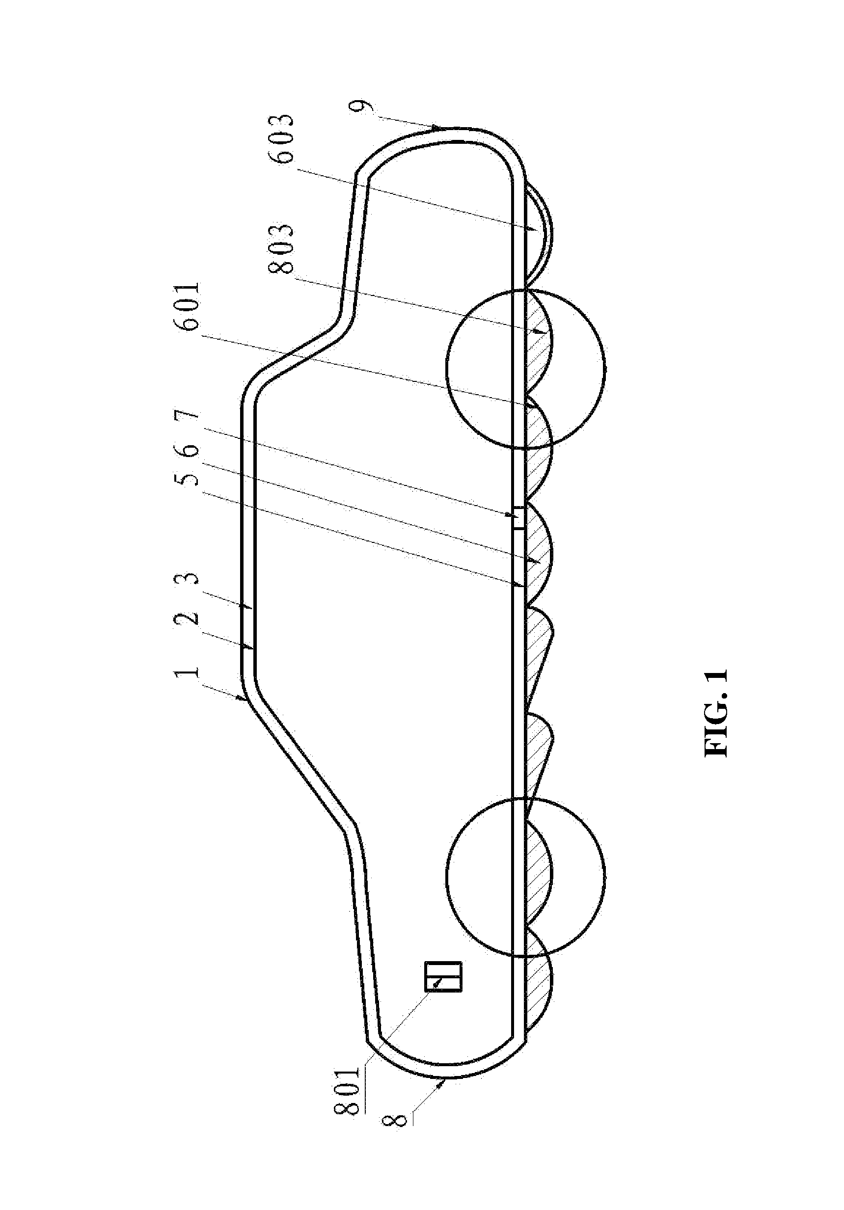
[0029]As shown in FIG. 1, an energy saving vehicle comprises a housing comprising an outer portion 1 and an inner portion 2. An air-flow channel 3 is disposed between the inner portion 2 and the outer portion 1 of the housing. The air-flow channel 3 communicates with an air outlet 9 arranged on a rear of the outer portion of the housing via a first air inlet 8 arranged on a front of the outer portion and a plurality of second air inlets 801 arranged on a periphery of the outer portion of the housing. A plurality of elastic devices 7 connected to one another are arranged between or around a bottom 5 of the housing and the inner portion 2 of the housing for reducing the vibration occurring in the travelling of the vehicle. Particularly, the inner portion of the housing comprises a curved upper surface and a flat lower surface, a lifting force is consequently resulted during the travelling of the vehicle; and the flexible connection of the elastic devices 7 functions in avoiding or att...
example 2
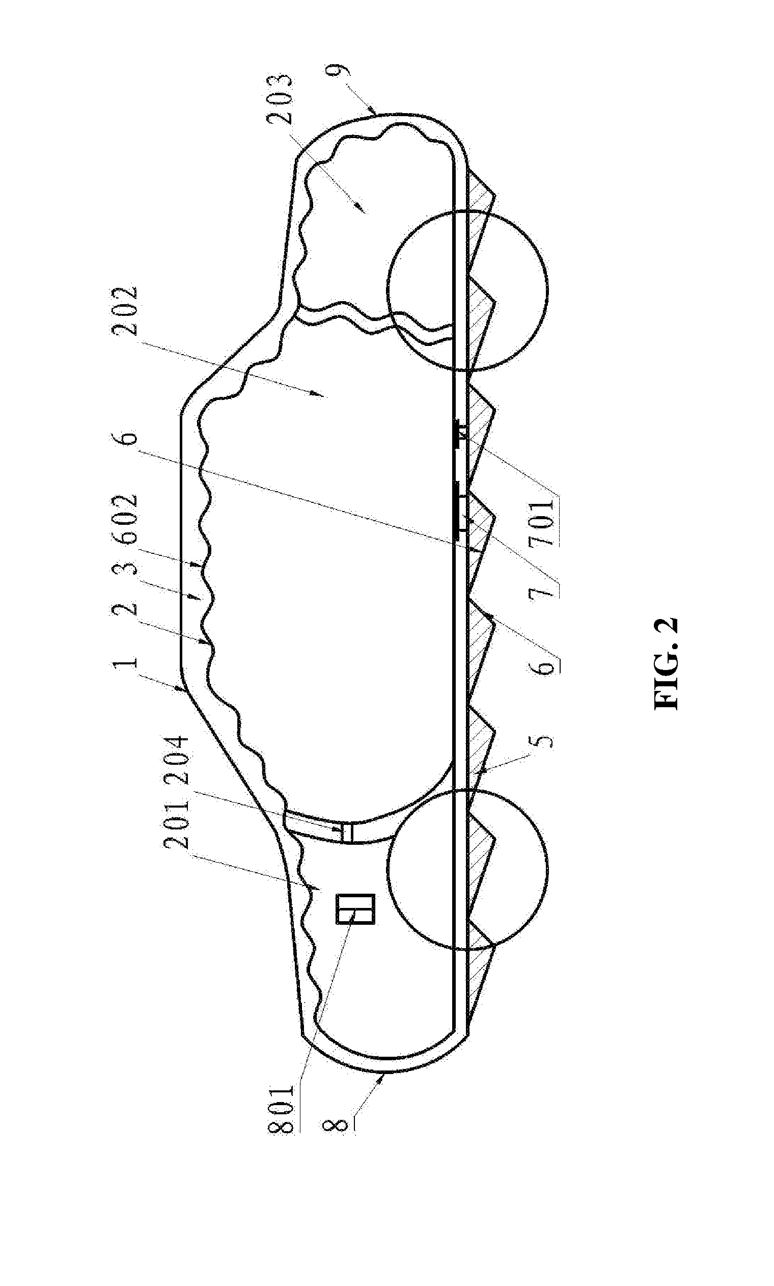
[0041]As shown in FIG. 2, the vehicle is the same as that in Example 1 except that the air-flow channel 3 communicating with the atmosphere via the first and the second air inlets 8, 801 divides the inner portion 2 of the housing into a first carrying cabin 201, a second carrying cabin 202, and a third carrying cabin 203. The carrying cabins are connected to one another via connecting pieces 204. When the vehicle travels, the air-flow channel 3 surrounds each carrying cabin, as each of the carrying cabins has a curved upper surface and a flat lower surface, the path of the air passing through the curved upper surface is different from that through the lower surface, resulting in a pressure difference and further producing a lifting force on each carrying cabin, and thus, a larger lifting force is produced under an overall action of the three carrying cabins 201, 202, and 203. The spoiler surface 6 can also be formed by a plurality of triangles.
[0042]The upper surface of each of the ...
example 3
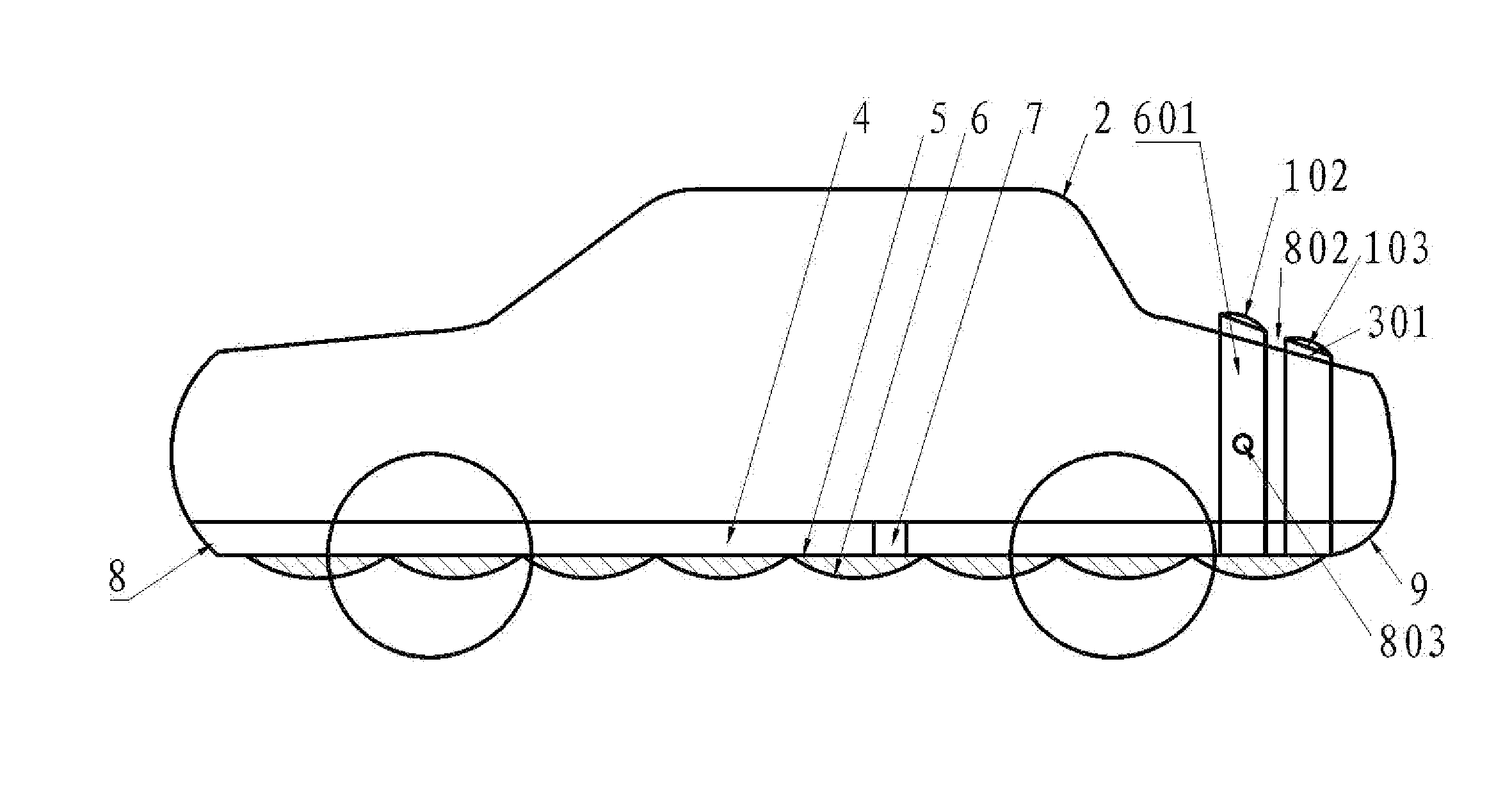
[0046]As shown in FIG. 3, the vehicle is the same as that in Example 2 except that the outer portion 1 of the housing of the vehicle comprises a plurality of independent spoilers 601 arranged on surfaces of the upper and the lateral of the vehicle according to the profile of the vehicle. A lower part of the spoiler 601 is connected to the bottom 5 of the housing. An open air-flow channel 4 is formed between the inner portion 2 and the bottom 5 of the housing, and the open air-flow channel 4 communicates with the first air inlet 8 and the air outlet 9. The spoiler comprises a curved upper surface 102 and a flat inner surface 103. An additional air-flow channel 301 is formed between the flat inner surfaces 103 of the spoiler and the inner portion2 of the housing. Pressure ports are formed between two adjacent spoilers and enable the additional air-flow channel 301 to communicate with the atmosphere.
[0047]In travelling of the vehicle, the air flows into the open air-flow channel 4 via ...
PUM
 Abstract
Description
Claims
Application Information
 - R&D
- Intellectual Property
- Life Sciences
- Materials
- Tech Scout
- Unparalleled Data Quality
- Higher Quality Content
- 60% Fewer Hallucinations
Browse by: Latest US Patents, China's latest patents, Technical Efficacy Thesaurus, Application Domain, Technology Topic, Popular Technical Reports.
© 2025 PatSnap. All rights reserved.Legal|Privacy policy|Modern Slavery Act Transparency Statement|Sitemap|About US| Contact US: help@patsnap.com


