Cam Engine

a cam engine and cam profile technology, applied in the direction of positive displacement liquid engines, piston pumps, machines/engines, etc., can solve the problem of reducing the possibility of breaking the contact between the main roller and the cam profile corresponding to the cam, and achieve the effect of improving the functional reliability of the apparatus

Active Publication Date: 2014-06-05
BAHNEV BOYAN
View PDF11 Cites 2 Cited by
  • Summary
  • Abstract
  • Description
  • Claims
  • Application Information

AI Technical Summary

Benefits of technology

[0009]The problem solved by the present invention is to provide technical solutions that improve t...

Problems solved by technology

The additional rollers include stoppers for limiting their movement along the axes of the main rollers, which additionally reduces the possibility ...

Method used


Image

  • Cam Engine
  • Cam Engine
  • Cam Engine

Examples


Embodiment Construction

[0050]According to the invention, different two- or one-piston cam engines can be realized, which execute different working cycles depending on the specific application of the engine that can function as a compressor, pump, internal combustion engine or a combination of the above-mentioned.

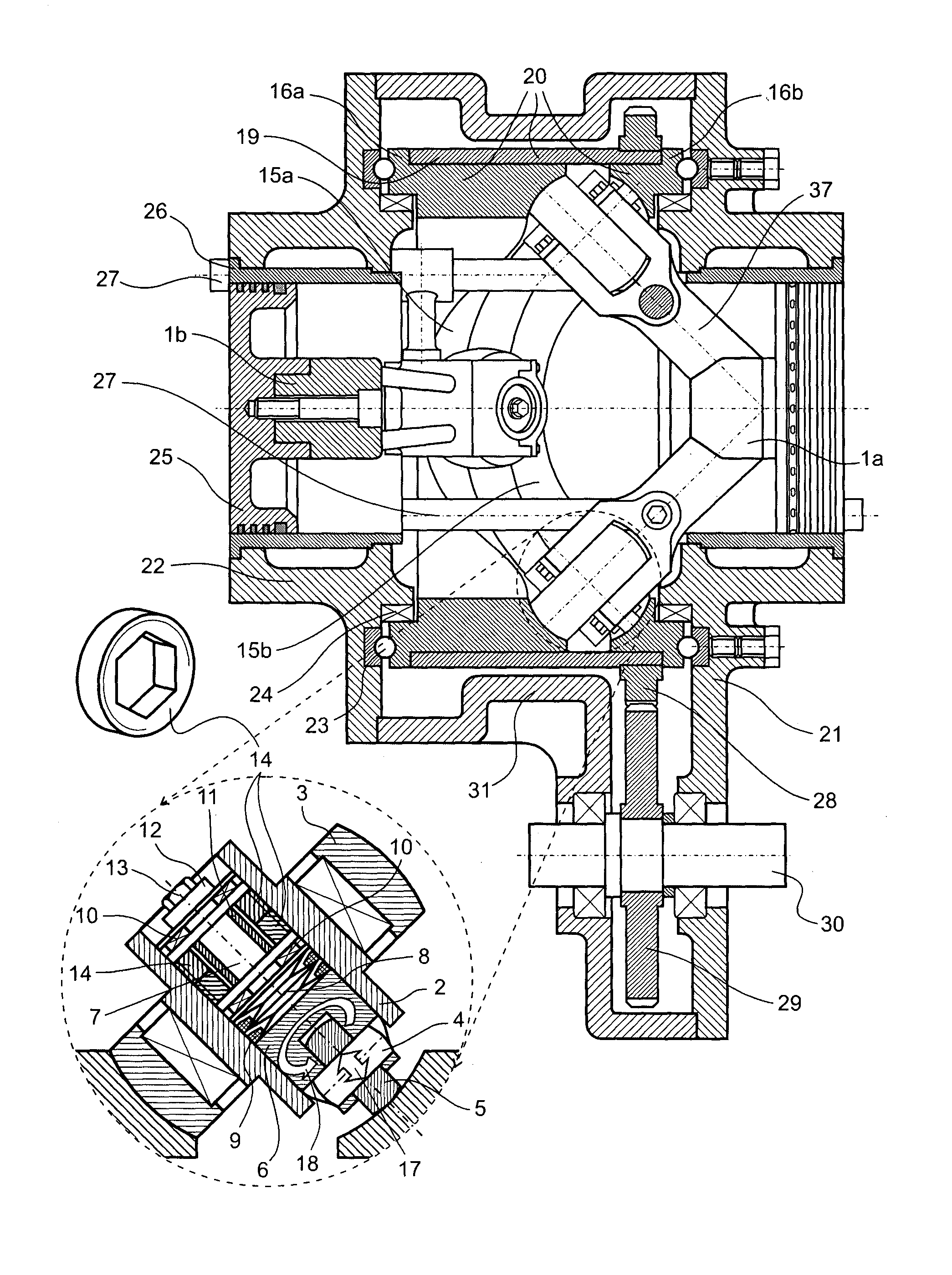
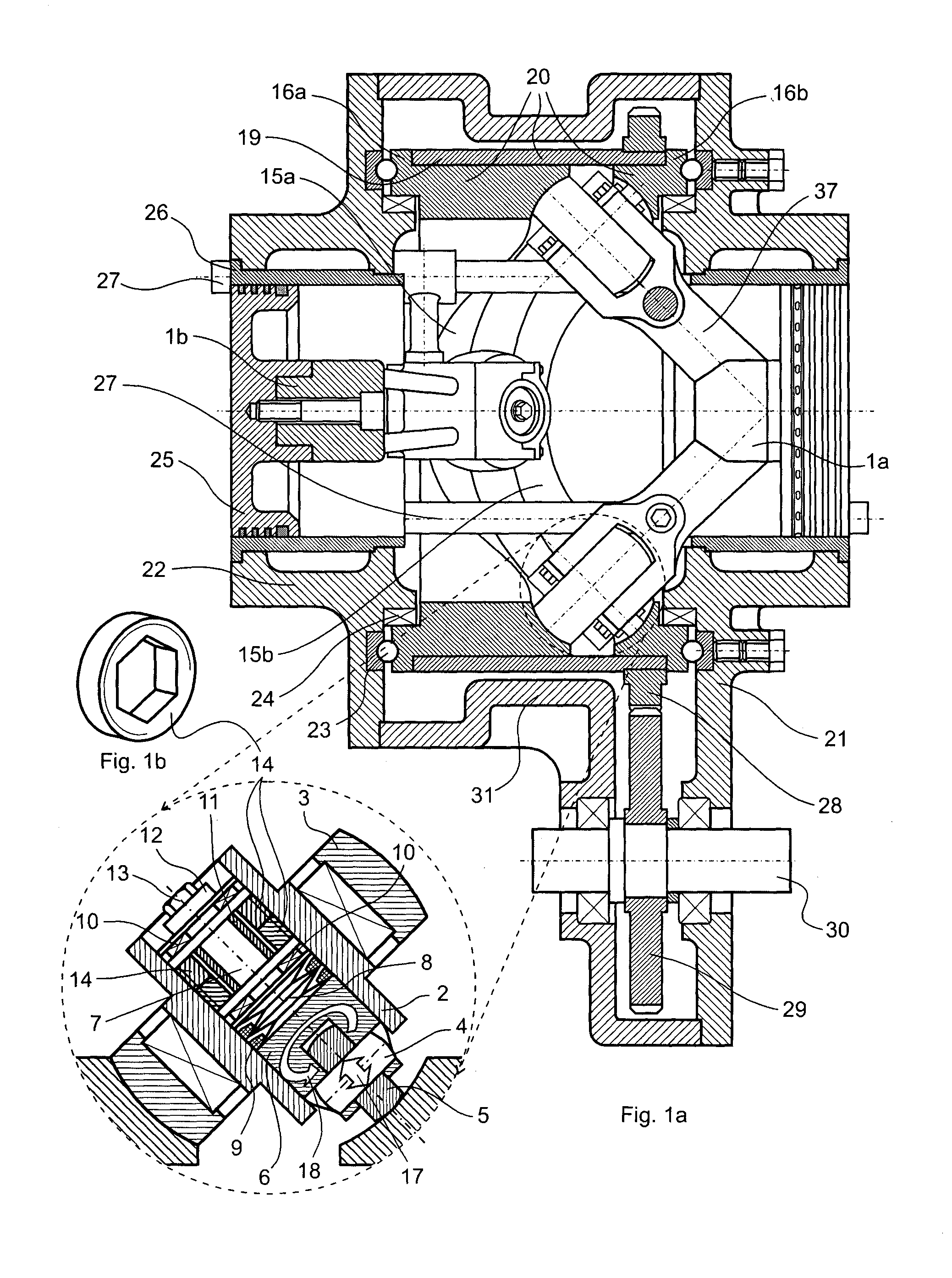
[0051]FIG. 1a and FIG. 1b show one embodiment of two-piston cam engine according to the invention. The engine comprises a tubular 3D cam 20, which is an assembly of cam bushings 16a and 16b and a tubular element 19 that orientates cam bushings 16a and 16b in such a way that their cam profiles 15a and 15b form a cam groove on the internal surface of the 3D cam 20. The engine comprises two identical followers 1a and 1b as well, each one of them having two arms 37. To the free ends of the arms 37, which in this case are shaped as bearing forks, main bearing journals 2 and main rollers 3 are mounted. The main bearing journals 2 are of tubular geometry and in their cylindrical cavities additional beari...


PUM


Abstract

The invention relates to a cam engine used in different field of the mechanical engineering, as internal-combustion engines, compressors, pumps etc. The cam engine comprises cylinders (26) with pistons (25), cylindrical tubular 3D cam (20) having a cam groove on the inner cylindrical surface and at least two asynchronously moving followers (1a and 1b) with arms (37) having main and additional rollers (3, 5).

Description

FIELD OF THE INVENTION[0001]The invention relates to a piston cam engine and particularly to an opposed-piston cam engine that may find application in different fields of mechanical engineering, e.g. internal combustion engines, compressors and etc. Engines, constructed according to this invention, could be used in various land, water and air vehicles, as well as in stationary aggregates.BACKGROUND OF THE INVENTION[0002]One of the common problems of the cam mechanisms is the relatively more rapid wear in comparison to the mechanisms which links are connected by hinged joints.[0003]The main reasons for the intensive wear of cam mechanisms are friction between the cam surface and the element, which is in contact with it; greater contact force transmitted by a very small area between the cam profile and the element in contact with the cam; as well as a break of contact between the cam and the element contacting with its profile and subsequent impact recovery of the contact between them...

Claims


Application Information

Patent Timeline
IPC IPC(8): F04B9/04
CPCF04B9/042F01B3/045F01B9/06F02B75/26F02B2075/025F01B13/045F02B57/00F02B75/265F02B57/08
Inventor BAHNEV, BOYAN
Owner BAHNEV BOYAN
Why Eureka
Try Eureka